Toyota Corolla (E120): Overhaul
Notice
:
- when using a vise, do not over tighten.
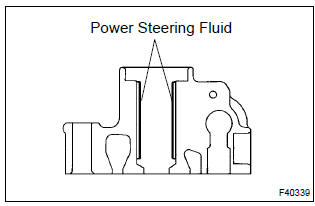
- When installing, coat the parts indicated by the arrows with power steering fluid .
1. Remove front wheel rh
2. Drain power steering fluid
3. Remove engine under cover rh
4. Remove fan and generator v belt
5. Disconnect oil reservoir to pump hose no.1
- remove the clip and disconnect the oil reservoir to pump hose no.1.
6. Disconnect pressure feed tube assy
- Using sst, disconnect the pressure feed tube assy.
Sst 09023–38400
- remove the bolt and disconnect the pressure feed tube clamp.
7. Remove vane pump assy
- Disconnect the oil pressure switch connector.
- remove the 2 bolts, nuts and vane pump assy.
8. Remove vane pump bracket rear
- remove the bolt and vane pump bracket rear.
9. Fix vane pump assy
- Using sst, hold the vane pump assy in a vise.
Sst 09630–00014 (09631–00132)
10. Remove power steering suction port union
- remove the bolt and power steering suction port union.
- remove the o–ring from the power steering suction port union.
11. Remove flow control valve
- remove the pressure port union.
- remove the o–ring from the pressure port union.
- remove the flow control valve and flow control valve compression spring.
12. Remove power steering oil pressure switch
Notice
: be careful so that oil pressure switch is not dropped or strongly damaged, however if it is damaged replace it with a new one. 13. Remove vane pump housing rear
- remove the 4 bolts and vane pump housing rear from the vane pump housing front.
- remove the o–ring from the vane pump housing front.
14. Remove w/pulley shaft sub–assy
- using a screwdriver, remove the snap ring from the w/ pulley shaft sub–assy.
- remove the w/ pulley shaft sub–assy.
15. Remove vane pump rotor
- remove the 10 vane plates.
- remove the vane pump rotor.
16. Remove vane pump cam ring
17. Remove vane pump side plate front
- Remove the side plate from the pump housing front.
- remove the o–ring from the side plate front.
- Remove the o–ring from the pump housing front.
18. Remove vane pump housing oil seal
- Using sst and a hammer, remove the vane pump housing
oil seal.
Sst 09631–10030
Notice
: be careful not to damage the pump housing.
19. Inspect oil clearance
- Using a micrometer and a caliper gauge, measure the oil
seal clearance.
Standard clearance:
0.021 – 0.043 Mm (0.0008 – 0.0017 In.) Maximum clearance: 0.07 Mm (0.0028 In.)
If it is more than the maximum, replace the vane pump assy.
20. Inspect vane pump rotor and vane plates
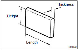
- Using a micrometer, measure the height, thickness and
length of the vane plates.
Minimum height: 7.6 Mm (0.299 In.) Minimum thickness: 1.405 Mm (0.0553 In.) Minimum length: 11.993 Mm (0.4722 In.)
- Using a feeler gauge, measure the clearance between a
side face of the vane pump rotor groove and vane plate.
Maximum clearance: 0.03 Mm (0.0012 In.)
If it is more than the maximum, replace the vane pump assy.
21. Inspect flow control valve
- Coat the flow control valve with power steering fluid and check that it falls smoothly into the flow control valve hole by its own weight.
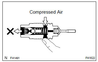
- Check the flow control valve for leakage. Close one of the holes and apply compressed air of 392 – 490 kpa (4 – 5 Kgf·cm2, 57 – 71 psi) into the opposite side hole, and confirm that air does not come out from the end holes.
If necessary, replace the vane pump assy.
22. Inspect flow control valve compression spring
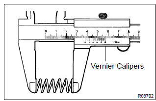
- Using vernier calipers, measure the free length of the
spring.
Minimum free length: 36.9 Mm (1.453 In.)
If it is not within the specification, replace the vane pump assy.
23. Inspect pressure port union
- if the union seat in the pressure port union is remarkably damaged and it may cause fluid leakage, replace the vane pump assy.
24. Install vane pump housing oil seal
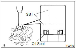
- Coat a new vane pump housing oil seal lip with power steering fluid.
- using sst and a press, install a new vane pump housing
oil seal.
Sst 09950–60010 (09951–00280), 09950–70010 (09951–07100)
Notice
: make sure that the vane pump housing oil seal is installed facing in the correct direction.
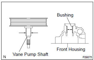
25. Install w/pulley shaft sub–assy
- Coat inside bushing surface of the vane pump housing front with power steering fluid.
- gradually insert the vane pump shaft.
Notice
: do not damage the vane pump housing oil seal lip in the vane pump housing front.
26. Install vane pump side plate front
- Coat a new o–ring with power steering fluid and install it to the vane pump housing front.
- Coat a new o–ring with power steering fluid and install it to the side plate front.
- Align the dent of the vane pump side plate front with that of the vane pump housing front, and install the vane pump side plate front.
Notice
: make sure that the side plate front is installed facing in the correct direction.
27. Install vane pump cam ring
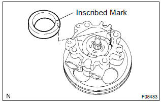
- Align the dent of the cam ring with that of the side plate front, and install the cam ring with the inscribed mark facing outward.
28. Install vane pump rotor
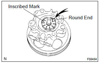
- Install the vane pump rotor with the inscribed mark facing outward.
- coat 10 vane plates with power steering fluid.
- install the vane plates with the round end facing outward.
- Using a snap ring expander, install a new snap ring to the w/ pulley shaft sub–assy.
29. Install vane pump housing rear
- coat a new o–ring with power steering fluid and install it to the pump housing rear.
- align the straight pin of the vane pump housing rear with the
dents of the vane pump cam ring, vane
pump side plate front and vane pump housing front, and install the vane pump
housing rear with the
4 bolts.
Torque: 22 nvm (220 Kgf·cm, 16 ft·lbf)
30. Inspect preload
- Check that the pump rotates smoothly without abnormal noise.
- temporarily install the service bolt.
Recommended service bolt: thread diameter: 10 mm (0.3937 In.) Thread pitch: 1.25 Mm (0.0492 In.) Bolt length: 50 mm (1.9685 In.)
- using a torque wrench, check the pump rotating torque.
Rotating torque:
0.27 Nvm (2.8 Kgf·cm, 2.4 ft·lbf) or less
31. Install power steering oil pressure switch
- coat a new o–ring with power steering fluid and install it to the power steering oil pressure switch.
- install the power steering oil pressure switch to the vane pump
assy.
Torque: 21 nvm (210 Kgf·cm, 15 ft·lbf)
32. Install flow control valve
- Coat the flow control valve compression spring and flow control valve with power steering fluid.
- install the flow control valve compression spring and flow control valve.
- coat a new o–ring with power steering fluid and install it to the pressure port union.
- install the pressure port union.
Torque: 69 nvm (700 Kgf·cm, 51 ft·lbf)
33. Install power steering suction port union
- coat a new o–ring with power steering fluid, and install it to the power steering suction port union.
- install the power steering suction port union with the bolt.
Torque: 12 nvm (120 Kgf·cm, 9 ft·lbf)
34. Install vane pump assy
- Install the vane pump assy with the 2 bolts and nuts.
Torque: 37 nvm (380 Kgf·cm, 27 ft·lbf)
- connect the oil pressure switch connector.
Notice
: be careful that the oil does not adhere to the connector.
35. Install vane pump bracket rear
- install the vane pimp bracket rear with the bolt.
Torque: 37 nvm (380 Kgf·cm, 27 ft·lbf)
36. Connect pressure feed tube assy
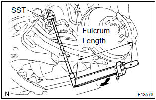
- Using sst, connect the pressure feed tube assy.
Sst 09023–38400
torque: 41 nvm (420 Kgf·cm, 30 ft·lbf)
Hint
:
- use a torque wrench with a fulcrum length of 345 mm (13.58 In.).
- This torque value is effective when sst is parallel to a torque wrench.
- connect the pressure feed tube clamp with the bolt.
Torque: 7.8 Nvm (80 Kgf·cm, 69 ft·lbf)
37. Connect oil reservoir to pump hose no.1
- connect the oil reservoir to pump hose no.1 With the clip.
38. Install fan and generator v belt
39. Install front wheel rh
torque: 103 nvm (1,050 Kgf·cm, 76 ft·lbf)
40. Add power steering fluid
41. Bleed power steering fluid
42. Inspect fluid leak
43. Install engine under cover rh


Other materials:
Adding a new phone number
Select “Add contacts” using . ●
Transferring all contacts from the cellular phone
Select “Overwrite all contacts” using
and press
(YES).
● Transferring one contact from the cellular phone
Select “Add one contact” using and
press (YES). ...
Child restraint system
fixed with an ISOFIX lower
anchorage (for Puerto
Rico)
■ ISOFIX lower anchorages
(ISOFIX child restraint system)
Lower anchorages are provided
for the outboard rear seats.
(Marks displaying the location of
the anchorages are attached to
the seats.)
■ When installing in the rear
outboard seats
Install the child restraint system
in accordance to the ...
SRS airbags
The SRS airbags inflate when the vehicle is subjected to certain
types of severe impacts that may cause significant injury
to the occupants. They work together with the seat belts to
help reduce the risk of death or serious injury.
SRS airbag system
■ Location of the SRS airbags
SRS front airbags ...