Toyota Corolla (E120) 2002–2008 Repair Manual / Starting & charging / Charging system / On–vehicle inspection
Toyota Corolla (E120): On–vehicle inspection
1. Check battery electrolyte level
- Check the electrolyte quantity of each cell (maintenance–free battery).
- If under the lower level, replace the battery (or add distilled water if possible) and check the charging system.
- check the electrolyte quantity of each cell (except maintenance–free battery).
- If under the lower level, add distilled water.
2. Check battery specific gravity (except maintenance–free battery)
- Check the specific gravity of each cell.
Standard specific gravity: 1.25 – 1.29 At 20 c (68 f)
Hint
: if the specific gravity is less than specification, charge the battery.
3. Check battery voltage
- After having driven the vehicle and in the case that 20 minutes have not passed after having stopped the engine, turn the ignition switch on and turn on the electrical system (headlight, blower motor, rear defogger etc.) For 60 seconds to remove the surface charge.
- turn the ignition switch off and turn off the electrical systems.
- measure the battery voltage between the negative (–)
and positive (+) terminals of the battery.
Standard voltage: 12.5 – 12.9 V at 20 c (68 f)
Hint
: if the voltage is less than specification, charge the battery.
- Check the indicator as shown in the illustration.
Hint
:
- blue: ok
- white: charging necessary
- red: insufficient water
4. Check battery terminals, fusible link and fuses
- Check that the battery terminals are not loose or corroded.
- check the fusible link, h–fuses and fuses for continuity.
5. Inspect drive belt
- Visually check the belt for excessive wear, frayed cords etc.
Hint
:
- if any defect has been found, replace the drive belt.
- Cracks on the rib side of a belt are considered acceptable.
If the belt has chunks missing from the ribs, it should be replaced.
- Check that it fits properly in the ribbed grooves.
Hint
: check with your hand to confirm that the belt has not slipped out of the groove on the bottom of the pulley.
6. Visually check alternator wiring
- check that the wiring is in good condition.
7. Listen for abnormal noises from alternator
- check that there is no abnormal noise from the alternator while the engine is running.
8. Inspect charge warning light circuit
- turn the ignition switch on. Check that the charge warning light comes on.
- start the engine. Check that the light goes off.
Hint
: if the light does not operate as specified, troubleshoot the charge warning light circuit.
9. Inspect charging circuit without load
- if a battery/alternator tester is available, connect the tester to the charging circuit as permanufacturer’s instructions.
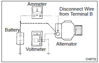
- If a tester is not available, connect a voltmeter to the charging circuit as follows.
- Disconnect to the wire from terminal b of the alternator and connect it to the negative (–) lead of the ammeter.
- Connect the positive (+) lead of the ammeter to terminal b of the alternator.
- Connect the positive (+) lead of the voltmeter to terminal b of the alternator.
- Ground the negative (–) lead of the voltmeter.
- Check the charging circuit (denso made).
- With the engine running from idle to 2,000 rpm,
check the reading on the ammeter and voltmeter.
Standard amperage: 10 a or less standard voltage: 12.9 – 14.9 V
10. Inspect charging circuit with load
- with the engine running at 2,000 rpm, turn on the high beam headlights and place the heater blower switch at ”hi”.
- check the reading on the ammeter.
Standard amperage: 30 a or more
Hint
:
- if the ammeter reading is less than standard amperage, repair the alternator.
- If the battery is fully charged, the indication will sometimes be less than standard amperage.


Other materials:
About this vehicle
1. Structural outline
2. Notice about vehicle condition when jacking up
vehicle
(a) notice for using jack and safety stand
(B) notice for using swing arm type lift
(C) notice for using plate type lift
3. Damage diagnosis
4. Components
(a) front bumper
(B) side mu ...
Replacement
1. Work for preventing gasoline from spilling out
2. Remove engine under cover rh
3. Drain coolant
4. Remove front wheel rh
5. Remove cylinder head cover no.2
Remove the 2 nuts, 2 clips and cylinder head cover.
6. Remove air cleaner hose no.1
loosen the 2 air cleaner hose ...
Radio broadcast cannot be received (bad reception)
Inspection procedure
1 Check if radio auto–search functions properly
Check if the radio auto–search functions properly.
Perform the auto–search of the radio and check that it functions
normally.
Standard: the radio auto–search functions properly.
2 Check optional ...