Toyota Corolla (E120) 2002–2008 Repair Manual / Diagnostics / Sfi system / Camshaft position sensor ”a”
circuit / Inspection procedure
Toyota Corolla (E120): Inspection procedure
Hint
: read freeze frame data using the hand-held tester or the obd ii scan tool. Freeze frame data records the engine conditions when a malfunction is detected. When troubleshooting, it is useful for determining whether the vehicle was running or stopped, the engine was warmed up or not, the air–fuel ratio was lean or rich, etc. At the time of the malfunction.
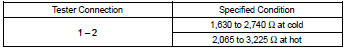
1 Inspect camshaft position sensor(resistance)
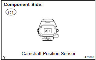
- Measure the resistance between the terminals of camshaft position sensor connector.
Standard:
Notice
: ”cold” and ”hot” shown above mean the temperature of the coils themselves. ”Cold” is from –10 c (14 f) to 50 c (122 f) and ”hot” is from 50 c (122 f) to 100 c (212 f).


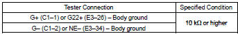
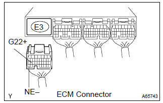
2 Check harness and connector(camshaft position sensor – ecm)
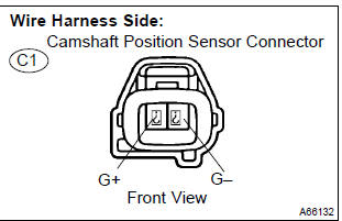
- Disconnect the c1 camshaft position sensor connector.
- disconnect the e3 ecm connector.
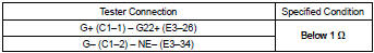
- check the resistance between the wire harness side connectors.
Standard (check for open):
Standard (check for short):
- Reconnect the ecm connector.
- reconnect the camshaft position sensor connector.

3 Check sensor installation(camshaft position sensor)
- Check the camshaft position sensor installation.


4 Check camshaft timing gear assy(teeth of plate)
- Check the teeth of the signal plate.


Replace ecm


Other materials:
Replacement
Hint:
installation is in the reverse order of the removal. But the installation is
indicated only when it has a point.
1. Remove radiator grille sub–assy
Remove the 2 bolts and clip.
using a screwdriver, remove the radiator grille.
Hint:
tape the screwdriver tip before use. ...
Inspection procedure
1 Check d squib circuit(airbag sensor assy center – horn button
assy)
Disconnect the negative (–) terminal cable from the battery,
and wait at least for 90 seconds.
disconnect the connectors between the airbag sensor
assy center and the horn button assy.
release the airbag ...
Circuit description
The side squib (rh) circuit consists of the airbag sensor assy center and
front seat airbag assy (rh).
It causes the srs to deploy when the srs deployment conditions are satisfied.
Dtc b0110/43 is recorded when a short is detected in the side squib (rh)
circuit.
Wiring diagram
...