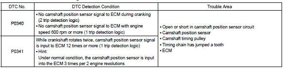
Toyota Corolla (E120) 2002–2008 Repair Manual / Diagnostics / Sfi system / Camshaft position sensor ”a”
circuit / Circuit description
Toyota Corolla (E120): Circuit description
The camshaft position sensor (g22+ signal) consists of a magnet, iron core and pickup coil.
The g22+ signal plate has 3 teeth on its outer circumference and is installed on the camshaft timing pulley.
When the camshafts rotate, the protrusion on the signal plate and the air gap on the pickup coil changes, causing fluctuations in the magnetic field and generating an electromotive force in the pickup coil.
The ne+ signal plate (crankshaft timing pulley) has 34 teeth and is installed to the crankshaft. The ne+ signal sensor generates 34 signals at every engine revolution. The ecm detects the crankshaft angle and the engine revolution based on the ne+ signals, and the cylinder and the angle of the vvt based on the combination of the g22+ and ne+ signals.
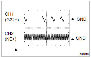
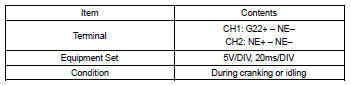
Reference: inspection using the oscilloscope.
Hint
: the correct waveform is as shown on the left.
Monitor description
If there is no signal from the camshaft position sensor despite the engine revolving, or if the rotation of the camshaft and the crankshaft is not synchronized, the ecm interprets this as a malfunction of the sensor.
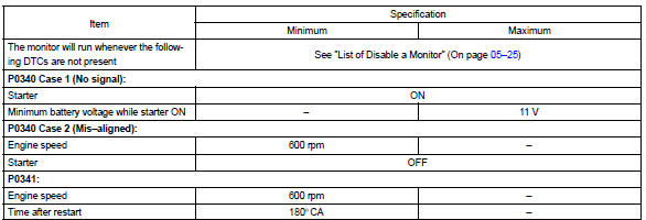
Monitor strategy
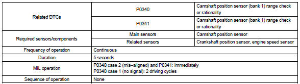
Typical enabling conditions
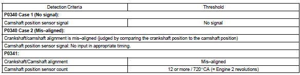
Typical malfunction thresholds
Component operating range

Wiring diagram
Refer to dtc p0335


Other materials:
Preparations to use wireless communication
The following can be performed using Bluetooth® wireless communication:
■ A portable audio player can be operated and listened to via multimedia system
■ Hands-free phone calls can be made via a cellular phone In order to use wireless
communication, register and connect a Bluetooth¬ ...
Vehicle control system
Ignition or starter switch assy
Replacement
1. Remove steering column cover
2. Remove ignition or starter switch assy
Disconnect the ignition switch connector and unlock
warning switch connector.
remove the 2 clamps.
remove the 2 screws and ignition switch.
Inspectio ...
Inspection procedure
Hint:
read freeze frame data using the hand-held tester or the obd ii scan tool.
Freeze frame data records the
engine conditions when a malfunction is detected. When troubleshooting, it is
useful for determining whether
the vehicle was running or stopped, the engine was warmed up or not, the ...