Toyota Corolla (E120) 2002–2008 Repair Manual / Windshield/windowglass/mirror / Combination meter / On–vehicle inspection
Toyota Corolla (E120): On–vehicle inspection
1. Inspect speedometer
- check the operation.
- Using a speedometer tester, inspect the speedometer fro allowable indication error and check the operation of the odometer.
Reference:
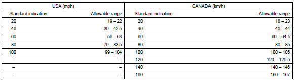
Notice
: tire wear and tire over or under inflation will increase the indication error.
- Check the deflection width of the speed meter indicator.
Reference: below 0.5 Km/h / 0.3 Mph
2. Inspect output signal of vehicle speed
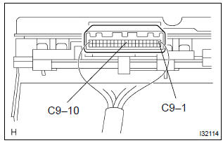
- Check for standard signal.
- While driving the vehicle at the speed of 10 km/h, check the voltage between the terminals c9–10 and c9–1 of the combination meter assy.
Standard: fluctuation between 10 to 14 v or less is repeated 7 times within 1 sec.
Notice
: check it with the ignition switch on and the connector connected.
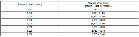
3. Inspect tachometer
- check the operation
- connect a tune–up test tachometer, and start the engine.
Notice
:
- reversing the connection of the tachometer will damage the transistors and diodes inside.
- When removing or installing the tachometer, be careful not to drop or subject it to heavy shocks.
- Compare the test and tachometer indications.
Dc 13.5 V, 25 c at (77 f)
4. Inspect fuel receiver gauge
- Inspect the circuit.
- Disconnect the connector from the sender gauge.
- Turn the ignition switch on, then check the position
of the receiver gauge needle.
Needle position: empty
- connect terminals 2 and 3 on the wire harness side
connector and turn the ignition switch on, then
check the position of the receiver gauge needle.
Needle position: full
5. Inspect fuel level warning
- inspect the circuit.
- Disconnect the connector from the sender gauge.
- Turn the ignition switch on, check the fuel level needle indicates empty and fuel level warning lights light on.
6. Inspect water temperature receiver gauge warning light
- inspect the circuit.
- Disconnect the connector from the sender gauge.
- Turn the ignition switch on, check the position of the water
temperature receiver gauge needle.
Needle position: cool
- connect between terminals on the wire harness side connector, then
check the position of the
water temperature receiver gauge needle.
Needle position: hot
7. Inspect low oil pressure warning ligh
t
- inspect the circuit.
- Disconnect the connector from the low oil pressure switch.
- Turn the ignition switch on.
- Connect the terminal of wire harness side connector and ground, then check the warning low oil pressure warning light.
Low oil pressure warning light: light on
8. Inspect low oil pressure switch
- check the continuity.
- Disconnect the connector from the low oil pressure switch.
- Check that continuity exists between terminal and ground.
Engine stopped: continuity engine running: no continuity
9. Inspect brake warning light
- inspect the parking brake warning light.
- Disconnect the connector from the parking brake switch and ground terminal on the wire harness side connector.
- Turn the ignition switch on and check that the warning light lights up.
- inspect the brake fluid level warning light.
- Disconnect the connector from the brake fluid level warning switch and connect terminals on the wire harness side connector.
- Turn the ignition switch on and check that the warning light lights up.
10. Inspect brake fluid level warning switch
- inspect the continuity.
- Remove the reservoir tank cap and strainer.
- Disconnect the connector.
- Check that the continuity exists between the terminals.
Float up (switch off): no continuity
- use syphon, etc., To take fluid out of the reservoir tank.
- Check that the continuity exists between the terminals.
Float down (switch on): continuity
- pour the fluid back in the reservoir tank.
11. Inspect light auto turn off buzzer
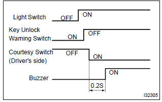
- Check the operation.
Hint
: when the key unlock warning and light auto turn off warning is output simultaneously, the key unlock warning precedes the other.
- Remove the ignition key with the tail light switch on
and the driver side door open and check for the
buzzer.
Buzzer sound: continuous
- while the buzzer is sounding, perform any of the following and check that the buzzer sound is stopped.
- Turn the tail light switch off.
- Close the driver side door.
- Insert the ignition key into the key cylinder.
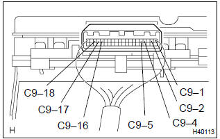
- Check the function.
- Remove the combination meter.
- Connect the position (+) lead from battery to terminal c9–5 and negative (–) lead to terminal c9–1 and c9–2.
- Connect the position (+) lead from battery to terminal
c9–18 and negative (–) lead to terminal c9–16
and c9–17, check that the buzzer sound.
Buzzer sound: continuous
- while the buzzer is sounding, connect the battery positive terminal to terminal c9–4 and check that the buzzer sound is stopped.
12. Inspect key unlock warning buzzer
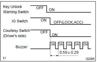
- Check the operation.
Hint
: when the key unlock warning and light auto turn off warning is output simultaneously, the key unlock warning precedes the other.
- While the driver side door is open, insert the ignition key, set the ignition switch to off (lock or acc) and check for the buzzer sound.
Buzzer sound: intermittent
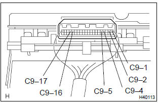
- Check the function.
- Remove the combination meter.
- Connect the position (+) lead from battery to terminal c9–5 and negative (–) lead to terminal c9–1 and c9–2.
- Connect the negative (–) lead to terminal c9–16
and c9–17, check that the buzzer sound.
Buzzer sound: intermittent
- While the buzzer is sounding, connect the battery positive terminal to terminal c9–4 and check that the buzzer sound is stopped.


Other materials:
Rear view monitor system precautions
■ Area displayed on screen
The rear view monitor system displays an image of the view from the bumper of
the rear area of the vehicle.
To adjust the image on the rear view monitor system screen.
• The area displayed on the screen may vary according to vehicle orientation
conditions.
...
RSA (Road Sign Assist)
The RSA system detects
specific road signs using
the front camera and/or navigation
system (when speed
limit information is available)
and warns the driver
via displays and buzzers.
WARNING
■For safe use
Driving safely is solely the
responsibility of the driver. Pay
careful attention to the su ...
Vehicle identification
■ Vehicle identification number
The vehicle identification number (VIN) is the legal identifier for your vehicle.
This is the primary identification number for your Toyota. It is used in registering
the ownership of your vehicle.
This number is stamped on the top left of the instrument p ...