Toyota Corolla (E120) 2002–2008 Repair Manual / Diagnostics / Cruise control system / Actuator mechanical malfunction / Inspection procedure
Toyota Corolla (E120): Inspection procedure
1 Inspect cruise control actuator assy
- Inspect the cruise control actuator arm locking operation.
- Turn the ignition switch to off.
- Disconnect the cruise control actuator assy connector.
- Connect the positive (+) lead from the battery to the terminal 3 (l) of cruise control actuator assy and the negative (–) lead to terminal 4 (gnd).
Notice
: do not connect the high tension cables to the wrong battery terminal. You will damage the cruise control actuator assy.
- Move the control plate by hand.
Ok: control plate does not move.
- inspect the cruise control actuator assy operation.
- Turn the ignition switch to off.
- Disconnect the cruise control actuator assy connector.
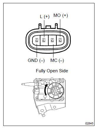
- Connect the positive (+) lead from the battery to terminals
1 (mo) and 3 (l) of cruise control actuator
assy, connect the negative (–) lead to terminals 2
(mc) and 4 (gnd) of cruise control actuator assy.
Ok: control arm moves to full open side.
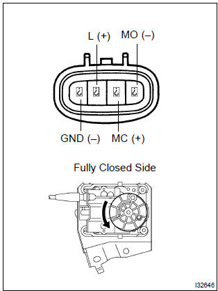
- Connect the positive (+) lead from the battery to terminals
2 (mc) and 3 (l) of cruise control actuator
assy, connect the negative (–) lead to terminals 1
(mo) and 4 (gnd) of cruise control actuator assy.
Ok: control arm moves to full close side.

2 Check harness and connector(between cruise control ecu assy and cruise control actuator assy)
- Check for open and short circuit in harness and connector between cruise control ecu assy and cruise control actuator assy (actuator motor)

Check and replace cruise control ecu assy


Other materials:
For vehicles equipped with srs airbag and seat belt pretensioner
Hint:
the vehicle is equipped with an srs (supplemental restraint system), such as the
horn button assembly,
the instrument panel passenger airbag assembly, the front seat airbag assembly,
the center airbag sensor
assembly, the front airbag sensor, the side airbag sensor and the seat belt
p ...
Side mudguard sub–assy lh
Replacement
Hint:
use the same procedures for the rh side and lh side.
1. Remove side mudguard sub–assy lh
Using a clip remover, remove the 8 retainers and 9 clips.
using a moulding remover, remove the mudguard.
2. Install side mudguard sub–assy lh
Install the mudgu ...
Checking the messages
1 Display the “Message Inbox” screen.
2 Select the desired message from the list.
3 Check that the message is displayed.
1 E-mails: Select “Mark Unread” or “Mark Read” to mark mail unread or read on
the message inbox screen.
This function is available when “Update Message Read S ...