Toyota Corolla (E120) 2002–2008 Repair Manual / Diagnostics / ABS with EBD system / Malfunction in abs ecu / Inspection procedure
Toyota Corolla (E120): Inspection procedure
1 Reconfirm dtc
- Check the dtc

2 Inspect skid control ecu connector securely connected


3 Inspect skid control ecu connector(ig1 terminal voltage)
In case of using hand–held tester:
- check the voltage condition output from the ecu displayed on the
hand–held tester.
Ok: ”normal” is displayed.
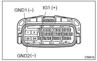
In case of not using hand–held tester:
- disconnect the skid control ecu connector.
- turn the ignition switch to on.
- measure voltage between terminals ig1 (3) and gnd (1,
23) of skid control ecu harness side connector.
Ok: oltage: 10 – 14 v


4 Inspect skid control ecu connector(gnd terminal continuity)
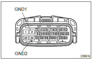
- Measure resistance between terminal gnd (s1–2, 24) of
skid control ecu harness side connector and body
ground.
Resistance: 1 Ω or less

Check and repair harness and connector
5 Go to combination meter system(abs warning light)
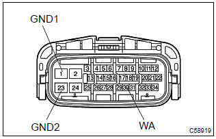
- Disconnect the skid control ecu connector.
- using service wire, connect terminals wa (30) and gnd (1, 23) of skid control ecu harness side connector.
- turn the ignition switch to on.
Ok: abs warning light goes off.

Check and replace brake actuator assy


Other materials:
Customer problem analysis
Hint:
in troubleshooting, the problem symptoms must be confirmed
accurately, meaning that all preconceptions
must be set aside in order to make an accurate judgement. To ascertain what
the problem symptoms
are, it is extremely important to ask the customer about the problem and
cond ...
Inspection procedure
Hint:
if dtc p0441 (purge flow), p0446 (vsv for ccv or vsv for pressure
switching valve), p0451, p0452
or p0453 is output with dtc p0442 or p0456 , first troubleshoot
dtc p0441, p0446, p0451, p0452 or p0453. If no malfunction is detected,
troubleshoot dtc
p0442 or p0456 next.
...
Inspection procedure
1 Check p squib circuit(airbag sensor assy center – instrument
panel passenger airbag assy)
Disconnect the negative (–) terminal cable from the battery,
and wait at least for 90 seconds.
disconnect the connectors between the airbag sensor
assy center and the instrument panel ...