Toyota Corolla (E120) 2002–2008 Repair Manual / Diagnostics / Supplemental restraint system / Seat belt buckle switch (lh)
malfunction / Inspection procedure
Toyota Corolla (E120): Inspection procedure
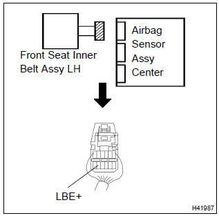
1 Check wire harness(airbag sensor assy center – front seat inner belt assy lh)
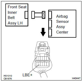
- Disconnect the negative (–) terminal cable from the battery, and wait at least for 90 seconds.
- disconnect the connectors between the airbag sensor assy center and the front seat inner belt assy (lh).
- for the connector (on the airbag sensor assy center side)
between the airbag sensor assy center and the front seat
inner belt assy (lh), measure the resistance between
lbe+ and body ground.
Ok: resistance: 1 mw or higher

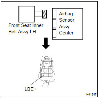
2 Check wire harness(airbag sensor assy center – front seat inner belt assy lh)
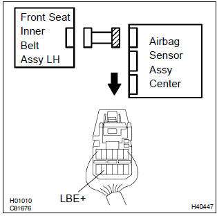
- Connect the negative (–) terminal cable to the battery, and wait at least for 2 seconds.
- turn the ignition switch to on.
- for the connector (on the airbag sensor assy center side)
between the airbag sensor assy center and the front seat
inner belt assy (lh), measure the voltage between lbe+
and body ground.
Ok: voltage: below 1 v

3 Check front seat inner belt assy lh
- Turn the ignition switch to lock.
- disconnect the negative (–) terminal cable from the battery, and wait at least for 90 seconds.
- connect the connector of the front seat inner belt assy (lh).
- unlock the seat belt for the front driver’s seat.
- for the connector (on the airbag sensor assy center side),
measure the resistance between lbe+ and body ground.
Ok: resistance: 1.0 Kw – 1.6 KΩ


4 Check front seat inner belt assy lh
- Lock the seat belt for the front driver’s seat.
- for the connector (on the airbag sensor assy center side),
measure the resistance between lbe+ and body ground.
Ok: resistance: 100 w – 500 Ω


5 Check air bag sensor assy center
Sst 09843–18040
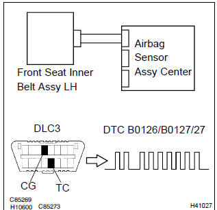
- Connect the connector to the airbag sensor assy center.
- connect the negative (–) terminal cable to the battery, and wait at least for 2 seconds.
- turn the ignition switch to on, and wait at least for 20 seconds.
- clear the dtc stored in memory .
- turn the ignition switch to lock, and wait at least for 20 seconds.
- turn the ignition switch to on, and wait at least for 20 seconds.
- check the dtc .
Ok: dtc b0126/b0127/27 is not output.
Hint
: codes other than code b0126/b0127/27 may be output at this time, but they are not relevant to this check.


Use simulation method to check


Other materials:
Circuit description
Refer to dtc p0130
Hint:
the ecm provides a pulse width modulated control circuit to adjust current
through the heater. The heated
oxygen sensor heater circuit uses a relay on the b+ side of the circuit.
Monitor description
The ecm uses the heated oxygen sensor information to regulate t ...
Replacement
Hint: components:
1. Precaution
2. Disconnect battery negative terminal
3. Remove parking brake hole cover sub–assy
4. Remove floor shift shift lever knob sub–assy (m/t transaxle)
5. Remove shifting hole cover sub–assy (m/t transaxle)
6. Remove console panel upper
7. Remove conso ...
When the contact is empty
You can transfer the phone numbers in a Bluetooth® phone to the system.
Operation methods differ between PBAP (Phone Book Access Profile) compatible
and PBAP incompatible Bluetooth® phones. If the cellular phone does not support
either PBAP or OPP (Object Push Profile) service, you cannot tra ...