Toyota Corolla (E120) 2002–2008 Repair Manual / Diagnostics / Sfi system / Evaporative emission control
system pressure sensor / Inspection procedure
Toyota Corolla (E120): Inspection procedure
Hint
:
- if different dtcs related to different systems that have terminal e2 as the ground terminal are output simultaneously, terminal e2 may be open.
- If dtc p0441 (purge flow), p0446 (vsv for ccv), p0451, p0452 or p0453 (evaporative pressure sensor) is output with dtc p0442 or p0456, troubleshoot dtc p0441, p0446, p0451, p0452 or p0453 first. If no malfunction is detected, troubleshoot dtc p0442 or p0456 next.
- Read freeze frame data using the hand-held tester or the obd ii scan tool. Freeze frame data records the engine conditions when a malfunction is detected. When troubleshooting, it is useful for determining whether the vehicle was running or stopped, the engine was warmed up or not, the air–fuel ratio was lean or rich, etc. At the time of the malfunction.
- If the engine run time in the freeze frame data is less than 200 seconds, carefully check the vapor pressure sensor.
1 Inspect ecm(vc voltage)
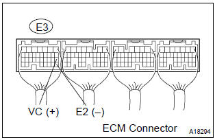
- Turn the ignition switch on.
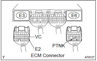
- measure the voltage between the terminals of the e3 ecm connector.
Standard:
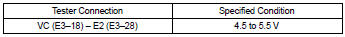


2 Inspect ecm(ptnk voltage)
- Turn the ignition switch on.
- measure the voltage between the terminals of the e3 and e6 ecm connectors.
- Disconnect the vacuum hose from the vapor pressure sensor.
Standard (1):

- Using the mityvac (hand–held vacuum pump), apply a vacuum of 4.0 Kpa (30 mmhg, 1.18 In.Hg) to the vapor pressure sensor.
Notice
: the vacuum applied to the vapor pressure sensor must be less than 66.7 Kpa (500 mmhg, 19.7 In.Hg).
Standard (2):

- Reconnect the vacuum hose.


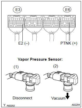
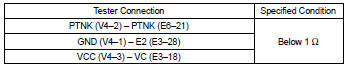
3 Check harness and connector(vapor pressure sensor – ecm)
- Disconnect the v4 vapor pressure sensor connector.
- disconnect the e3 and e6 ecm connectors.
- check the resistance between the wire harness side connectors.
Standard (check for open):
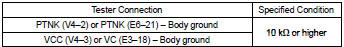
Standard (check for short):
- Reconnect the ecm connectors.
- reconnect the vapor pressure sensor connector.

Replace vapor pressure sensor assy


Other materials:
Automatic transaxle assy (atm)
Precaution
The automatic transaxle is composed of highly precision–finished
parts, necessitating careful
inspection before reassembly because even a small nick could cause fluid
leakage or affect
the performance. The instructions here are organized so that you work on
only o ...
Circuit description
The p squib (2nd step) circuit consists of the airbag sensor assy center and
instrument panel passenger
airbag assy.
It causes the srs to deploy when the srs deployment conditions are satisfied.
Dtc b1185/57 is recorded when a short is detected in the p squib (2nd step)
circuit.
Wiri ...
Body rocker panel moulding lh
Replacement
Hint:
use the same procedures for the rh side and lh side.
1. Remove body rocker panel moulding lh
Remove the 8 retainers.
using a screwdriver, remove the moulding.
Hint:
tape the screwdriver tip before use.
remove the 7 clips from the moulding.
2. Insta ...