Toyota Corolla (E120) 2002–2008 Repair Manual / Diagnostics / Sfi system / Throttle/pedal position
sensor/switch ”a” circuit / Inspection procedure
Toyota Corolla (E120): Inspection procedure
Hint
:
- if different dtcs related to different systems that have terminal e2 as the ground terminal are output simultaneously, terminal e2 may be open.
- Read freeze frame data using the hand-held tester or the obd ii scan tool. Freeze frame data records the engine conditions when a malfunction is detected. When troubleshooting, it is useful for determining whether the vehicle was running or stopped, the engine was warmed up or not, the air–fuel ratio was lean or rich, etc. At the time of the malfunction.
Hand–held tester:
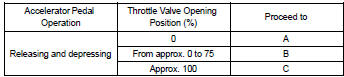
1 Read value of hand–held tester(throttle valve opening percentage)
- Connect the hand–held tester to the dlc3.
- turn the ignition switch on.
- select the item ”diagnosis / enhanced obd ii / data list / etcs / throttle pos” and read its value displayed on the hand–held tester.
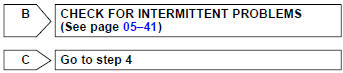
Result:

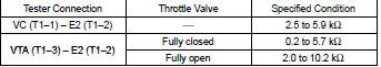
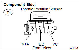
2 Inspect throttle position sensor
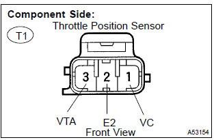
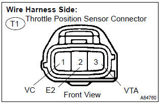
- Disconnect the t1 throttle position sensor connector.
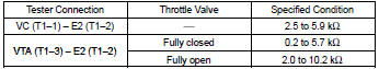
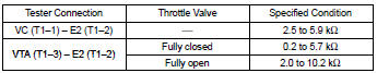
- measure the resistance between the terminals of the throttle position sensor.
Standard
- Reconnect the throttle position sensor connector.


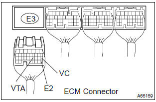
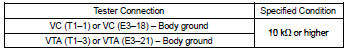
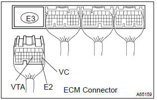
3 Check harness and connector(ecm – throttle position sensor)
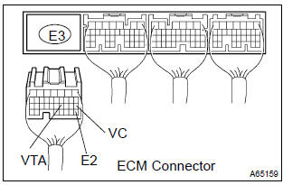
- Disconnect the e3 ecm connector.
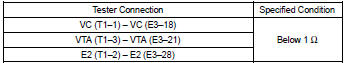
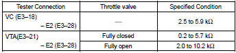
- measure the resistance between the terminals of the e3 ecm connector.
Standard:
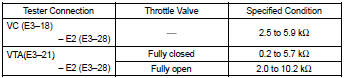
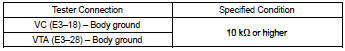
- Check the resistance between the terminals of the e3 ecm connector.
Standard (check for short):
- Reconnect the ecm connector.


Replace ecm
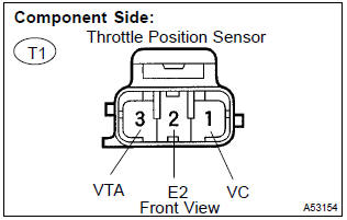
4 Inspect throttle position sensor
- Disconnect the t1 throttle position sensor connector.
- measure the resistance between the terminals of the throttle position sensor.
Standard:
- Reconnect the throttle position sensor connector.


5 Check harness and connector(ecm – throttle position sensor)
- Disconnect the e3 ecm connector.
- disconnect the t1 throttle position sensor connector.
- check the resistance between the wire harness side connectors.
Standard (check for open):
Standard (check for short):
- Reconnect the throttle position sensor connector.
- reconnect the ecm connector.


Replace ecm
Obd ii scan tool (excluding hand–held tester):
1 Inspect throttle position sensor
- Disconnect the t1 throttle position sensor connector.
- measure the resistance between the terminals of the throttle position sensor.
Standard:
- Reconnect the throttle position sensor connector.


2 Check harness and connector(throttle position sensor – ecm)
- Disconnect the e3 ecm connector.
- measure the resistance between the terminals of the e3 ecm connector.
Standard:
- Check the resistance between the terminals of the e3 ecm connector.
Standard (check for short):

- Reconnect the ecm connector.


Other materials:
Adjustment
1. Headlight aim only
place the vehicle in the following conditions.
The area around the headlight is not deformed.
The vehicle is parked on a level surface.
Tire inflation pressure is in the specified value .
A driver is in the driver’s seat and the vehicle is in a state rea ...
Overhaul
1. Remove roof headlining assy
2. Remove sliding roof glass sub–assy
using a torx wrench (t25), remove the 4 screws the sliding roof
glass.
pull the glass upward to remove it.
3. Remove sliding roof weatherstrip
4. Remove sliding roof drive gear sub–assy
Notice:
...
Replacement
1. Drain engine oil
remove the oil pan drain plug and drain the engine oil.
2. Removal & installation chain sub–assy
3. Remove chain vibration damper no.1
remove 2 bolts and chain vibration damper no. 1.
4. Remove oil pump assy
Remove the 5 bolts.
rem ...