
Toyota Corolla (E120): Inspection
1. Cooling fan relay
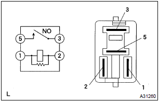
- Inspect the cooling fan relay continuity.
- Using an ohmmeter, check that there is continuity
between terminals 1 and 2.
If there is no continuity, replace the relay.
- Check that there is no continuity between terminals
3 and 5.
If there is continuity, replace the relay.
- Apply battery voltage across terminals 1 and 2.
- Using an ohmmeter, check that there is continuity
between terminals 3 and 5.
If there is no continuity, replace the relay.
2. Cooling fan relay no.2
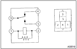
- Inspect the cooling fan relay continuity.
- Using an ohmmeter, check that there is continuity
between terminals 1 and 2.
If there is no continuity, replace the relay.
- Using an ohmmeter, check that there is continuity
between terminals 3 and 4.
If there is no continuity, replace the relay.
- Check that there is no continuity between terminals
3 and 5.
If there is continuity, replace the relay.
- Apply battery voltage across terminals 1 and 2.
- Using an ohmmeter, check that there is continuity
between terminals 3 and 5.
If there is no continuity, replace the relay.
3. Cooling fan resistor
- using an ohmmeter, measure the resistance between the terminals.
Resistance: 1.17 – 1.43 W at 20 c (68 f)


Other materials:
Light control switch circuit
Wiring diagram
Inspection procedure
1 Check headlamp dimmer switch assy (light control switch)
2 Check wire harness (tvip ecu light control switch)
Disconnect the tvip ecu and light control switch connectors.
check the continuity between the terminals of the tvip
e ...
Changing engine switch
modes
Modes can be changed by
pressing the engine switch with
brake pedal released. (The
mode changes each time the
switch is pressed.)
OFF*1
The emergency flashers can be
used.
ACC*2
Some electrical components such
as the audio system can be used.
"ACCESSORY" will be displayed
on the multi-info ...
Key confinement prevention function does not work
properly (unlock warning switch circuit)
Circuit description
The unlock warning switch turns on when the key is inserted in the ignition
key cylinder and the door courtesy
switch turns on when the driver’s door is opened, and the integration relay
monitors both switches conditions.
According to these switches conditions, the int ...