Toyota Corolla (E120) 2002–2008 Repair Manual / Diagnostics / Wireless door lock control system / Terminals of ecu
Toyota Corolla (E120): Terminals of ecu
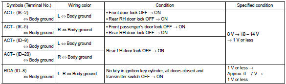
1. Inspect integration relay
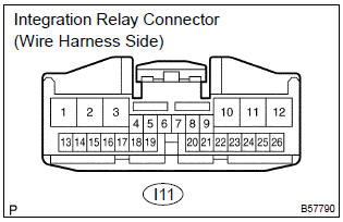
- Disconnect the connector from the integration relay.
- check the continuity between each terminal of the disconnected connector and the body ground, as shown in the illustration and table.
Standard:
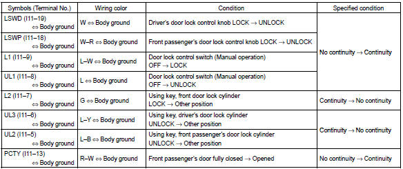
If the result is not as specified, the vehicle’s side may malfunction.
- reconnect the connector and check the voltage between each terminal and the body ground, as shown in the illustration and table.
Standard:
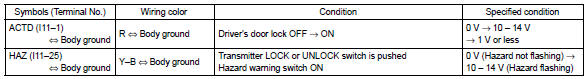
If the result is not as specified, the integration relay may malfunction.
2. Inspect instrumental panel j/b (integration relay)
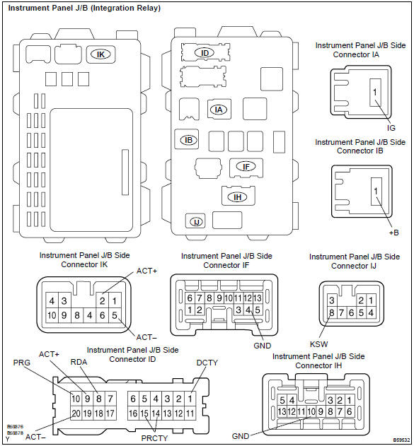
- Disconnect the connectors ia, ib, id, if, ih and ij of the instrument panel j/b.
- check the continuity between each terminal of the disconnected connectors and the body ground, as shown in the illustration and table.
Standard:
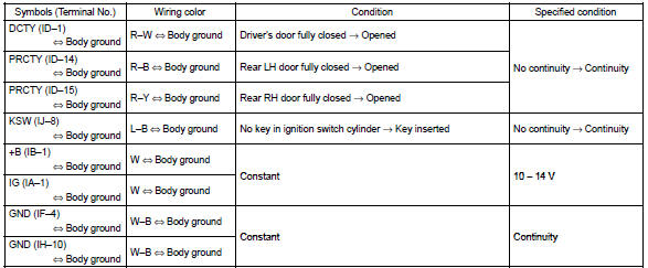
If the result is not as specified, the vehicle’s side may malfunction.
- reconnect the connectors and check the voltage between each terminal and the body ground, as shown in the illustration and table.
Standard:
If the result is not as specified, the integration relay or instrument panel j/b assembly may malfunction.
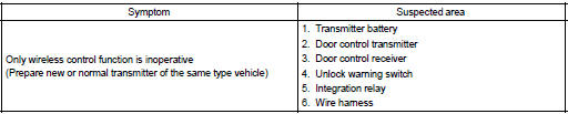
Problem symptoms table


Other materials:
Check and replace ecu
Notice:
start an inspection of the connector from the backside
of the connector on the wire harness side with
the connector connected to the ecu.
When no measurement condition is specified, perform
the inspection with the engine stopped and also
the ignition switch on.
First check the ec ...
Overhaul
1. Precaution
2. Disconnect battery negative terminal
3. Inspect place front wheels facing straight ahead
4. Remove horn button assy
Notice:
if the airbag connector is disconnected with the ignition
switch being at on, dtcs will be recorded.
using a torx socket wrench, loosen the ...
On–vehicle inspection
1. Connect hand–held tester:
connect the hand–held tester to the dlc3.
start the engine and run it at idle.
select the active test mode on the hand–held tester.
Hint:
please refer to the hand–held tester operator’s manual for further details.
2. Inspect actua ...