Toyota Corolla (E120): Circuit description
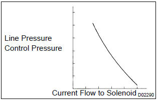
The throttle pressure that is applied to the primary regulator valve (which modulates the line pressure) causes the solenoid valve slt, under electronic control, to precisely and minutely modulate and generate the line pressure according the extent of the accelerator pedal depressed or the output of engine power.
This controls the line pressure and provides smooth shifting.
Upon receiving a signal of the throttle valve opening angle, the ecm controls the line pressure by sending a predetermined (*) duty ratio to the solenoid valve, modulating the line pressure and generating throttle pressure.
(*): Duty ratio the duty ratio is the ratio of the period of continuity in one cycle.
For example, if a is the period of continuity in one cycle, and b is the period of non–continuity, then duty ratio=a/(a+b) x 100 (%)
Monitor description
The linear solenoid valve (slt) controls the transmission line pressure for smooth transmission operation based on signals from the throttle position sensor and the vehicle speed sensor. The ecm adjusts the duty cycle of the slt solenoid valve to control hydraulic line pressure coming from the primary regulator valve.
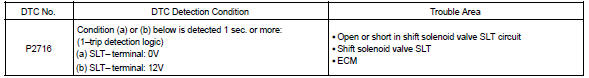
Appropriate line pressure assures smooth shifting with varying engine outputs. When an open or short in the linear solenoid valve (slt) circuit is detected, the ecm interprets this as a fault. The ecm will turn on the mil.
Monitor strategy
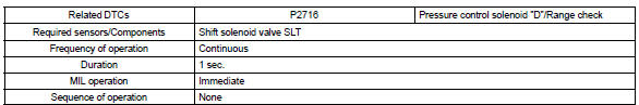
Typical enabling condition
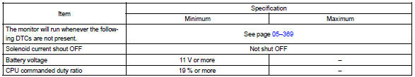
Typical malfunction thresholds

Component operating range

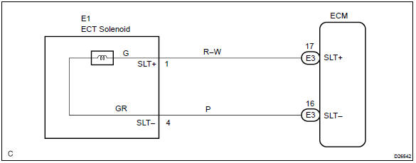
Wiring diagram


Other materials:
On–vehicle inspection
1. Check fuel pump operation
Connect the hand–held tester to the dlc3.
turn the ignition switch on and hand–held tester main
switch on.
Notice:
do not start the engine.
select the active test mode on the hand–held tester.
please refer to the hand–held te ...
Pre–check
1. Srs warning light check
Turn the ignition switch to the on position and check that
the srs warning light lights up.
check that the srs warning light goes out after approx.
6 Seconds.
Hint:
when the ignition switch is at on and the srs warning
light remains on or flashes, the ...
How to proceed with troubleshooting
1 Vehicle brought to workshop
2 Customer problem analysis
3 Check and clear dtcs and freeze frame data
4 Problem symptom confirmation
Symptom does not occur: go to
step 5
Symptom occurs: go to step 6
5 Symptom simulation
6 Dtc check
There is no
output: go to step 7
There is outp ...