Toyota Corolla (E120): Circuit description
Refer to dtc p0115
|
Dtc no. |
Dtc detection condition |
Trouble area |
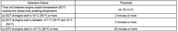
| P0125 | If the engine coolant temperature (ect) was less than –6.6 °C (20 °F) when starting the engine, and 20 minutes after the engine start, the ect sensor still indicates below 20 °C (68 °F) |
|
| If the ect was between –6.6 °C (20 °F) and 10 °C (50 °F) when start, 5 minutes after the start, the ect sensor still indicates below 20 °C (68 °F) | ||
| If the ect was greater than 10 °C (50 °F) when starting the engine, and 2 minutes after the engine start, ect sensor still indicates below 20 °C (68 °F) |
Monitor description
The engine coolant temperature (ect) sensor is used to monitor the temperature of the engine coolant. The resistance of the sensor varies with the actual coolant temperature. The ecm applies a voltage to the sensor and the varying resistance of the sensor causes the signal voltage to vary. The ecm monitors the ect signal voltage after engine start–up. If, after sufficient time has passed, the sensor still reports that the engine is not warm enough for closed–loop fuel control, the ecm interprets this as a fault in the sensor or cooling system.
Example: the engine coolant temperature was 0 c (32 f) at engine start. After 5 minutes running time, the coolant temperature sensor still indicates that the engine is not warm enough to begin air–fuel ratio feedback control.
The ecm interprets this as a fault in the sensor or cooling system and will set a dtc.
Monitor strategy
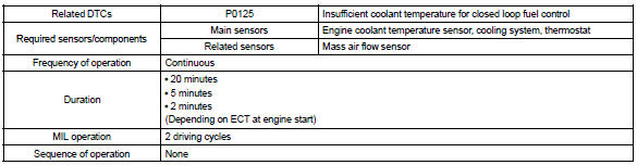
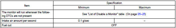
Typical enabling conditions
Typical malfunction thresholds
Wiring diagram
Refer to dtc p0115


Other materials:
Phone screen
To display the screen shown below, press the
switch on the steering wheel or the
button.
Several functions are available to operate on each screen that is displayed by
selecting the 4 tabs.
1 Device name
2 Bluetooth® connection status
■ Telephone switch
■ Microphone
υ ...
Replacement
1. Remove engine under cover rh
2. Drain coolant
3. Remove fan and generator v belt
4. Remove generator assy
Disconnect the wire clamp from the wire clip on the rectifire
end frame.
remove the rubber cap and nut, and disconnect the alternator
wire.
disconnect the ...
Child restraint systems
Before installing a child
restraint system in the vehicle,
there are precautions
that need to be observed,
different types of child
restraint systems, as well as
installation methods, etc.,
written in this manual.
Use a child restraint system
when riding with a small child
that cannot properly use a ...