Toyota Corolla (E120): Circuit description
Refer to dtc p0120
|
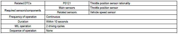
Dtc no. |
Dtc detection condition |
Trouble area |
| P0121 | The following condition is met 4 times. After the vehicle speed has exceeded 19 mph (30 km/h) once, the throttle position sensor output value is out of normal range when the throttle valve is closed at 0 km/h |
|
Monitor description
The throttle position sensor varies its resistance with the angle of the throttle valve. The ecm applies a regulated reference voltage to the throttle position sensor “+” terminal and calculates the angle of the throttle valve based on the voltage present at the throttle position sensor “signal” terminal.
When the throttle valve is near the fully closed position, the output voltage of the throttle position sensor is low. When it is near the fully open position, the output voltage is high.
The ecm checks the indicated angle of the throttle valve during “stop and go” conditions. If the indicated angle (or voltage) in the “closed throttle” position is out of the specified range, the ecm interprets this as a malfunction in the throttle position sensor and sets a dtc.
Monitor strategy
Typical enabling condition
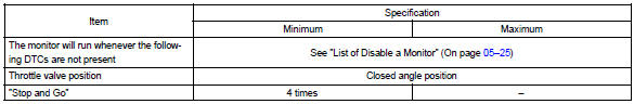
”Stop and go” is defined as follows: ”stop” indicates a vehicle speed of 0 mph (0 km/h). ”Go” indicates a vehicle speed of 18.6 Mph (30 km/h).
Typical malfunction thresholds

Component operating range


Other materials:
Overhaul
1. Remove generator pulley
Sst 09820–63010 (09820–06010, 09820–06020)
Hint:
Hold sst 1 – a with a torque wrench, and tighten sst 1
– b clockwise to the specified torque.
Torque: 39 nvm (398 Kgf·cm, 29 ft·lbf)
Notice:
check that sst is secured to the rotor shaft.
...
Outside temperature display
The temperature display shows temperatures within the range of -40°F (-40°C)
to 122°F (50°C).
► Type A
► Type B
► Type C
► Type D
■The outside temperature is displayed when
►Vehicles without a smart key system
The engine switch is in the “ON ...
Circuit description
The airbag front rh sensor circuit consists of the airbag sensor assy center
and airbag front rh sensor.
Dtc b1156/b1157/15 is recorded when a malfunction is detected in the airbag
front rh sensor circuit.
Wiring diagram
...