Toyota Corolla (E120) 2002–2008 Repair Manual / Automatic transmission / trans / Transmission valve body assy (atm)
Toyota Corolla (E120): Transmission valve body assy (atm)
Replacement
1. Remove engine under cover lh
2. Drain automatic transaxle fluid
- remove the drain plug, gasket and drain atf.
- install a new gasket and drain plug.
Torque: 17.5 Nvm (178 Kgf·cm, 13 ft·lbf)
3. Remove automatic transaxle oil pan sub–assy
- Remove the 18 bolts, oil pan and gasket.
Notice
: some fluid will remain in the oil pan. Remove all pan bolts, and carefully remove the oil pan assembly. Discard the gasket.
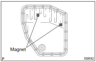
- remove the 2 magnets from oil pan.
- Examine particles in pan.
- Remove the magnets and use them to collect any
steel chips. Look carefully at the chips and particles
in the pan and the magnet to anticipate what type
of wear you will find in the transaxle.
Steel (magnetic): bearing, gear and plate wear brass (non–magnetic): bearing wear
4. Remove valve body oil strainer assy
- Remove the 3 bolts and oil strainer.
Notice
: be careful as some fluid will come out with the oil strainer.
5. Remove transmission valve body assy
- Disconnect the 4 solenoid connecters.
- Remove the bolt and manual detent spring.
- Remove the 17 bolts.
- While disconnecting the manual valve connecting rod from the manual valve lever, remove the valve body with the manual valve together.
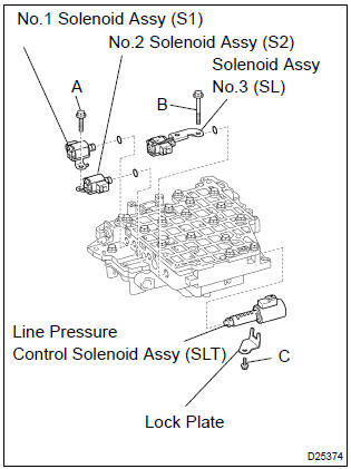
- Remove the 2 bolts and 3 solenoid valves.
- remove the 3 o–rings from each of the solenoid valves.
- remove the bolt, lock plate and line pressure control valve.
6. Install transmission valve body assy
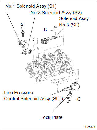
- Coat 3 new o–rings with atf and install them to each solenoid valves.
- install the no.1 And no.2 Solenoid valves with the bolt.
- install the no.3 Solenoid valve with the bolt.
- install the line pressure control solenoid valve and lock
plate with the bolt.
Torque:
bolt a: 11 n·m (110 kgf·cm, 8 ft·lbf) bolt b: 11 n·m (110 kgf·cm, 8 ft·lbf) bolt c: 6.5 N·m (66 kgf·cm, 58 in.Vlbf) bolt length:
bolt a: 25 mm (0.984 In.) Bolt b: 60 mm (2.362 In.) Bolt c: 12 mm (0.472 In.)
- While connecting the manual valve connecting rod to the manual valve lever, install the valve body with the manual valve together.
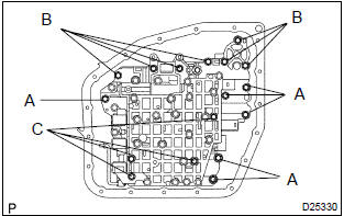
- Install the 17 bolts.
Bolt length:
bolt a: 20 mm (0.79 In.) Bolt b: 28 mm (1.10 In.) Bolt c: 50 mm (1.97 In.) Torque: 10 n·m (100 kgf·cm, 7 ft·lbf)
- Install the manual detent spring and bolt.
Torque: 10 n·m (100 kgf·cm, 7 ft·lbf)
- Connect the 4 solenoid connectors.
7. Install valve body oil strainer assy
- Install the oil strainer with the 3 bolts.
Bolt length:
a bolt: 12 mm (0.47 In.) B bolt: 20 mm (0.79 In.) Torque: 10 n·m (100 kgf·cm, 7 ft·lbf)
8. Install automatic transaxle oil pan sub–assy
- Install the 2 magnets to the oil pan.
- Install a new gasket to the oil pan and install them to the transaxle.
- install the 18 bolts.
Torque: 5.3 N·m (55 kgf·cm, 48 in.Vlbf)
9. Install engine under cover lh
10. Add automatic transaxle fluid
11. Inspect automatic transaxle fluid


Other materials:
On–vehicle inspection
1. Install lspv gauge (sst) and bleed air
remove the bleeder plugs from the front and rear brake cylinder.
install the lspv gauge (sst), and bleed the air.
Sst 09709–29018
2. Raise master cylinder pressure and check rear wheel cylinder pressure
Hint:
when inspectin ...
Wiper & washer
Preparation
Sst
Recomended tools
Equipment
...
Rear wheel alignment
Inspection
1. Inspect tire
2. Measure vehicle height
Notice:
before inspecting the wheel alignment, adjust the vehicle height to the
specified value.
3. Inspect toe–in
Toe–in:
usa, canada:
Mexico:
If the toe–in is not within the specified value, inspect and replace
the susp ...