Toyota Corolla (E120) 2002–2008 Repair Manual / Brake / Skid control sensor
Toyota Corolla (E120): Skid control sensor
Replacement
Hint
: replace the rh side by the same procedure as the lh side.
1. Remove rear wheel
2. Remove rear brake drum sub–assy
3. Disconnect skid control sensor wire
- Disconnect the skid control sensor wire connector from the skid control sensor.
4. Remove rear axle hub & bearing assy lh
5. Remove skid control sensor
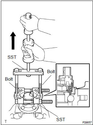
- Mount the rear axle hub in a soft jaw vise.
Notice
: replace the axle hub assembly if it is dropped or a strong shock is given to it.
- using a pin punch and hammer, drive out the 2 pins and remove the 2 attachments from sst.
- using sst and 2 bolts (diameter: 12 mm, pitch: 1.5 Mm),
remove the skid control sensor from the rear axle hub.
Sst 09520–00031 (09520–00040), 09521–00020, 09950–00020
N
otice
:
- if a damage is inflicted to the sensor rotor, replace the axle hub assembly.
- Do not scratch the contacting surface of axle hub and speed sensor.
6. Install skid control sensor
- clean the contacting surface of the axle hub and a new
speed sensor.
Notice
: do not stick any foreign objects to the sensor rotor.
- place the speed sensor on the axle hub so that the connector makes the lowest position under the on–vehicle condition.
- Using sst and press, install the new speed sensor to the
axle hub.
Sst 09214–76011
7. Install rear axle hub & bearing assy lh
8. Connect skid control sensor wire
- Connect the skid control sensor wire connector to the skid control sensor.
9. Install rear brake drum sub–assy
10. Install rear wheel
torque: 103 nvm (1,050 Kgf·cm, 76 ft·lbf)
11. Inspect and adjust rear wheel alignment
12. Check abs speed sensor signal


Other materials:
Using the storage features
List of storage features
1 Glove box
2 Bottle holders
3 Console box
4 Cup holders
CAUTION
■Items that should not be left in the storage spaces
Do not leave glasses, lighters or spray cans in the storage spaces, as this
may cause the following when cabin temperature becomes high: ...
Inspection procedure
1 Check voltage at ig2 of airbag sensor assy center
Disconnect the negative (–) terminal cable from the battery,
and wait at least for 90 seconds.
disconnect the connector of the airbag sensor assy center.
connect the negative (–) terminal cable to the battery,
and wa ...
Front differential oil seal
Replacement
1. Drain manual transaxle oil
torque: 39.2 Nvm (400 Kgf·cm, 29 ft·lbf)
2. Remove front wheels
3. Remove engine under cover lh
4. Remove engine under cover rh
5. Drain transaxle oil
6. Remove front drive shaft assy lh
sst 09520–01010, 09520–24010 (09520–32040)
7. R ...