Toyota Corolla (E120): Repair
1. Steering off center repair procedure
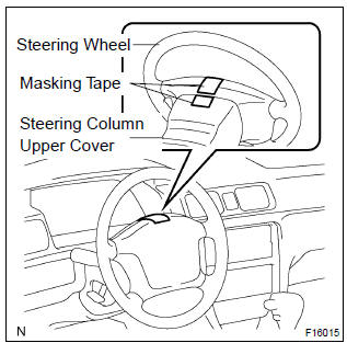
- Inspect steering wheel off center.
- Apply masking tape on the top center of the steering wheel and steering column upper cover.
- Driving the vehicle on a straight line for 100 meters at a constant speed of 35 mph (56 km/h), and hold the steering wheel to maintain the course.
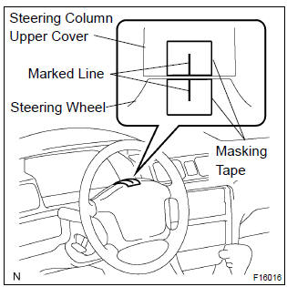
- Draw a line on the masking tape as shown in the illustration.
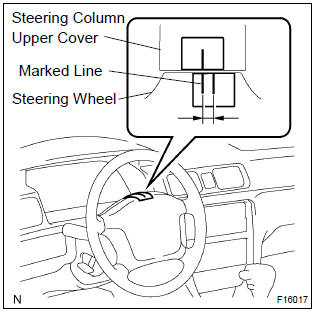
- Turn the steering wheel to its straight position.
Hint
: refer to the upper surface of the steering wheel, steering spoke and srs airbag line for the straight position.
- Draw a new line on the masking tape or the steering wheel as shown in the illustration.
- Measure the distance between the 2 lines on the masking tape of the steering wheel.
- Convert the measured distance to steering angle.
Measured distance 1 mm (0.04 In.) = Steering angle approximately 1 deg.
Hint
: make a note of the steering angle.
- adjust steering angle.
Notice
: the adjustment method for steering angle varies depending on the models. Check whether it is type a or b.
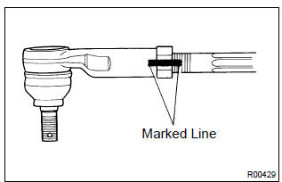
- Draw a line on the rh and lh tie rod and rack ends where it can easily be seen.
- Using a paper gauge, measure the distance from rh and lh tie rod ends to the rack end screws.
Hint
:
- measure the rh side and lh side.
- Make a note of the measured values.
- Remove the rh and lh boot clips from the rack boots.
- Loosen the rh and lh lock nuts.
- Turn the rh and lh rack end by the same amount
(but in different directions) according to the steering
angle.
1 Turn 360 deg. Of rack end (1.5 Mm (0.059 In.) Horizontal movement) – 12 deg. Of steering angle.
- Tighten the rh and lh lock nuts by the specified
torque.
Torque: 74 n·m (750 kgf·cm, 54 ft·lbf)
Notice
: make sure that the difference in length between rh and lh tie rod ends and rack end screws are within 1.5 Mm (0.059 In.).
- Install the rh and lh boot clips.


Other materials:
Monitor description
The battery supplies electricity to the ecm even when the ignition switch is
off. This electricity allows the
ecm store data such as dtc history, freeze frame data, fuel trim values, and
other data. If the battery voltage
falls below a minimum level, the ecm will conclude that there is a fault ...
Circuit description
Hint:
these dtcs indicate a malfunction related to the primary circuit.
If dtc p0351 is displayed, check the no.1 Ignition coil with igniter
circuit.
If dtc p0352 is displayed, check the no.2 Ignition coil with igniter
circuit.
If dtc p0353 is displayed, check the no.3 Ignition coil ...
Terminals of ecu
Oscilloscope wave (*1)
Hint:
terminal: od – gnd
gauge set: 5 v / div, 50 ms / div
condition: during cruise control driving o/d switch on.
...