Toyota Corolla (E120): Overhaul
Hint
: component:
1. Discharge refrigerant from refrigeration system
sst 07110–58060 (07117–58080, 07117–58090, 07117–78050, 07117–88060, 07117–88070, 07117–88080)
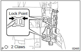
2. Disconnect cooler refrigerant suction hose no.1
- Install sst to piping clamp.
Sst 09870–00015
Hint
: confirm the direction of the piping clamp claw and sst using the illustration showing on the caution label.
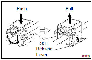
- Push down sst and release the clamp lock.
Notice
: be careful not to deform the tube, when pushing sst.
- pull sst slightly and push the release lever, then remove the piping clamp with sst.
- remove the piping clamp from sst.
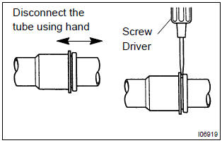
- Disconnect the cooler refrigerant suction hose no. 1.
Notice
:
- do not use tools like screwdriver to remove the tube.
- Cap the open fittings immediately to keep moisture or dirt out of the system.
3. Disconnect cooler refrigerant liquid pipe a
sst 09870–00015
Hint
: disconnect in the same way as the cooler refrigerant suction hose no. 1.
4. Disconnect heater inlet water hose
- Using pliers, grip the claws of clip and slide the clip and disconnect the heater inlet water hose.
5. Disconnect heater outlet water hose
Hint
: disconnect in the same way as the heater inlet water hose.
6. Remove instrument panel sub–assy lower
Hint
: refer to the instructions for removal of the instrument panel sub–assy lower.
7. Remove instrument panel lwr pad insert lh
- Remove the 3 screws and instrument panel lwr pad insert lh.
8. Remove instrument panel brace sub–assy no.1
- Remove 2 clips and take up the floor carpet.
Hint
: take up the floor carpet as small as the instrument panel brace sub–assy no. 1 Can be removed.
- Remove the clamp and floor shift parking lock cable assy.
- Remove the screw.
- remove the bolt, nut and instrument panel brace sub– assy no. 1.
9. Remove air duct no.1
- Release the 2 fitting claws, remove the air duct no. 1.
10. Remove air duct no.2
- Remove the screw.
- release the 2 fitting claws, remove the air duct no. 2.
11. Remove air duct rear no.3 (W/ cold area)
- Release the 6 fitting claws, remove the air duct rear no.3.
12. Remove air duct rear no.4 (W/ cold area)
- Remove 2 clips and take up the floor carpet.
Hint
: take up the floor carpet as small as the air duct rear no.4 Can be removed.
- Release the 6 fitting claws, remove the air duct rear no.4.
13. Remove heater to register duct no.2
- Remove the 2 clips and heater to register duct no. 2.
14. Remove heater to register duct no.1
- Remove the 2 clips and heater to register duct no. 1.
15. Remove defroster nozzle assy
- Release the 3 fitting claws, remove the defroster nozzle assy.
16. Disconnect defroster damper control cable sub–assy
- Disconnect the outer cable from the clamp.
- disconnect the inner cable and defroster damper control cable sub–assy.
Notice
:
- be careful not to bend the cable wire.
- If the cable wire bends, the heater control & accessory assy operationality becomes worse.
17. Disconnect airmix damper control cable sub–assy
- Disconnect the outer cable from the clamp.
- disconnect the inner cable and air mix damper control cable sub–assy.
Notice
:
- be careful not to bend the cable wire.
- If the cable wire bends, the heater control & accessory assy operationality becomes worse.
18. Disconnect ecm
- Remove the 2 bolts and disconnect the ecm.
Notice
:
- do not apply excessive force to the connecter of the ecm.
- Do not give any impact to the ecm.
19. Remove instrument panel to cowl brace center
- Remove the 2 nuts and instrument panel to cowl brace center.
20. Disconnect steering column assy
- Disconnect the connector, remove the 2 clamps.
- Remove the 3 bolts, disconnect the steering column assy.
21. Remove instrument panel reinforcement
- Remove the 8 screws and 2 earth wires from the instrument panel reinforcement.
- Disconnect the 6 clamps and wire harness.
- Remove the 6 bolts and instrument panel reinforcement.
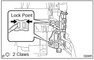
22. Remove air conditioner unit assy
- Release the 2 fitting claws, disconnect the connector holder.
Hint
: release the claw while pressing the lock part in the arrow direction.
- Disconnect the connector from the blower w/ fan motor sub–assy.
- Disconnect the connector from the damper servo sub– assy.
- Disconnect the connector from the cooler thermistor no.
- Remove the 4 nuts, bolt and air conditioner unit assy.
23. Remove air filter case
- Release the 2 fitting claws, remove the air filter case.
24. Remove air filter
- Remove the air filter from the air conditioner unit assy.
Hint
: removing only the glove compartment door assy makes it possible and install the air filter.
25. Remove damper servo sub–assy
- Remove the 2 screws and damper servo sub–assy.
Hint
: removing only instrument panel sub–assy upper and heater to register duct no. 1 Makes it possible and install the damper servo sub–assy.
26. Remove blower w/fan motor sub–assy
- Remove the 3 screws and blower w/ fan motor sub–assy.
Hint
: removing only the ecm makes it possible and install the blower w/fan motor sub–assy.
27. Remove blower resistor
- Disconnect the connector.
- remove the 2 screws and blower resistor.
Hint
: removing only the ecm makes it possible and install the blower resistor.
28. Remove heater piping cover
- Release the 3 fitting claws, remove the heater piping cover.
29. Remove heater radiator unit sub–assy
- Release the 3 fitting claws, remove the heater piping clamp and heater radiator unit sub–assy
30. Remove cooler thermistor no.1
- Remove the clamp.
- release the fitting claw, remove the 2 screws and heater case.
- Release the fitting claw, remove the 5 screws and heater case.
- Remove the cooler thermistor no. 1 From the cooler evaporator sub–assy no. 1.
31. Remove air conditioning tube assy
- Remove the cooler evaporator assy from the heater case.
- remove the packing.
- Using a hexagon wrench 5.0 Mm (0.20 In.), Remove the 2 hexagon bolts and air conditioning tube assy.
- remove the 2 o–rings from the air conditioning tube assy.
32. Remove cooler expansion valve
- Remove the cooler expansion valve from the cooler evaporator sub–assy no. 1.
- remove the 2 o–rings from the cooler evaporator sub– assy no. 1.
Hint
: removing only instrument panel sub–assy upper, heater to register duct no. 1 And heater case makes it possible and install the cooler expansion valve.
33. Remove cooler evaporator sub–assy no.1
34. Remove cooler unit drain hose no.1
35. Install cooler expansion valve

- Lubricate 2 new o–rings with compressor oil and install
them to the cooler expansion valve.
Compressor oil: nd–oil 8 or equivalent
- install the cooler expansion valve from cooler evaporator sub–assy no. 1.
36. Install air conditioning tube assy
- Lubricate 2 new o–rings with compressor oil and install
them to the air conditioning tube assy.
Compressor oil: nd–oil 8 or equivalent
- using a hexagon wrench 5.0 Mm (0.20 In.), Install the air
conditioning tube assy with the 2 hexagon bolts.
Torque: 3.5 Nvm (35 kgfvcm, 30 in.Vlbf)
- Install the packing.
Hint
: securely attach so that the gap in the packing will not be mode.
- install the cooler evaporator assy to the heater case.
37. Install cooler thermistor no.1
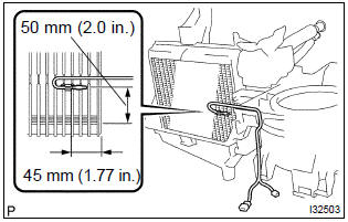
- Install the cooler thermistor no. 1 At the shown position on the illustration.

- Install the heater case with the claw and 5 screws.
- Install the heater case with the claw and 2 screws.
38. Install air filter
- Install the air filter to the air conditioner unit assy.
39. Install air conditioner unit assy
- Install the air conditioner unit assy with the 4 nuts and bolt.
Torque: 9.8 Nvm (100 kgfvcm, 87 in.Vlbf)
Notice
: tighten the nuts and bolt in following order shown in the illustration to install the air conditioner unit assy.
- Connect the connector to the cooler thermistor no. 1.
- Connect the connector to the damper servo sub–assy.
- Connect the connector to the blower w/ fan motor sub– assy.
- Install the 2 fitting claws, connect the connector holder.
40. Install ecm
- Install the ecm with the 2 bolts.
Torque: 3.0 Nvm (30 kgfvcm, 26 in.Vlbf)
Notice
:
- do not apply excessive force to the connecter of the ecm.
- Do not give any impact to the ecm.
41. Install instrument panel sub–assy lower
42. Install heater control & accessory assy
43. Install defroster damper control cable sub–assy
- Set the arm in face position.
- install the inner cable end to the control lever with the arm in face position.
- install the outer cable to the cable clamp while slightly pressing it in the direction of the arrow.
Notice
:
- be careful not to bend the cable wire.
- If the cable wire bends, the heater control & accessory assy operationality becomes worse.
Hint
: operating the mode control lever, check that it properly stops at both ends of face and def and no recoil is identified.
44. Install airmix damper control cable sub–assy
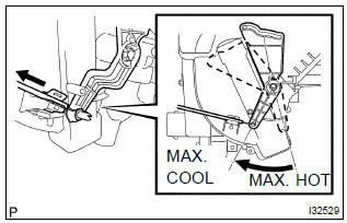
- Set the arm in max. Cool position.
- install the inner cable end to the control lever with the arm in max. Cool position.
- install the outer cable to the cable clamp while slightly pressing it in the direction of the arrow.
Notice
:
- be careful not to bend the cable wire.
- If the cable wire bends, the heater control & accessory assy operationality becomes worse.
Hint
: operating the temperature control lever, check that it properly stops at both ends of max. Cool and max. Hot and no recoil is identified.
45. Remove heater control & accessory assy
46. Install instrument panel sub–assy upper
47. Install heater outlet water hose
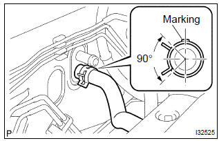
- Using pliers, grip the claws of clip and slide the clip and connect the heater outlet water hose.
Notice
:
- the clip is installing so that the projection of the clip may go into the 90 to a direction position.
- Marking of hose is installed upward by vehicle.
48. Install heater inlet water hose
Hint
: connect in the same way as the heater outlet water hose.
49. Install cooler refrigerant suction hose no.1
- Lubricate a new o–ring with compressor oil and install
them to the hose.
Compressor oil: nd–oil 8 or equivalent
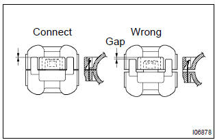
- install the cooler refrigerant suction hose no. 1 And piping clamp.
Hint
: after connection, check the fitting for claw of the piping clamp. 50. Install cooler refrigerant liquid pipe a
- lubricate a new o–ring with compressor oil and install them to the
pipe.
Compressor oil: nd–oil 8 or equivalent
- install the cooler refrigerant liquid pipe a and piping clamp.
Hint
: after connection, check the fitting for claw of the piping clamp.
51. Add coolant
52. Check engine coolant leak
53. Charge refrigerant
sst 07110–58060 (07117–58060, 07117–58070, 07117–58080, 07117–58090, 07117–78050, 07117–88060, 07117–88070, 07117–88080), 07117–48130, 07117–48140 specified amount: 490 30 g (17.28 1.06 Oz.)
54. Warm up engine
55. Inspect leakage of refrigerant


Other materials:
Speed sensor front lh
Replacement
Hint:
replace the rh side by the same procedure as the lh side.
1. Remove front wheel
2. Remove front fender liner lh
3. Remove speed sensor front lh
Disconnect the speed sensor wire harness clamp from
the body.
disconnect the speed sensor connector.
Remo ...
Inspection procedure
1 Check p/t squib(lh) circuit(airbag sensor assy center – front seat
outer belt assy lh)
Disconnect the negative (–) terminal cable from the battery,
and wait at least for 90 seconds.
disconnect the connectors between the airbag sensor
assy center and the seat belt pretensio ...
Calculation formula for your vehicle
1 Cargo capacity
2 Total load capacity (vehicle capacity weight)
When 2 people with the combined weight of A lb. (kg) are riding in your vehicle,
which has a total load capacity (vehicle capacity weight) of B lb. (kg), the available
amount of cargo and luggage load capacity will be C lb. (kg ...