Toyota Corolla (E120): Overhaul
1. Precaution
2. Disconnect battery negative terminal
3. Inspect place front wheels facing straight ahead
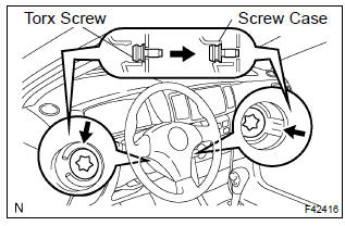
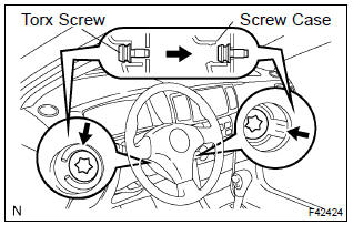
4. Remove horn button assy
Notice
: if the airbag connector is disconnected with the ignition switch being at on, dtcs will be recorded.
- using a torx socket wrench, loosen the 2 torx screws until the groove along the screw circumference catches on the screw case.
- Pull out the horn button assy from the steering wheel.
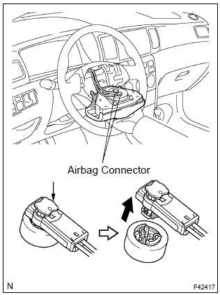
- using a screwdriver, release the lock part of each airbag connector and disconnect the 2 airbag connectors.
Notice
: when removing the horn button assy, take care not to pull the airbag wire harness.
Caution
:
- when storing the horn button assy, keep the upper surface of the pad facing upward.
- Never disassemble the horn button assy.
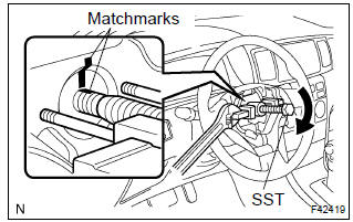
5. Remove steering wheel assy
- Disconnect the connector.
- remove the steering wheel assy set nut.
- place matchmarks on the steering wheel assy and main shaft assy.
- using sst, remove the steering wheel assy.
Sst 09950–50013 (09951–05010, 09952–05010, 09953–05020, 09954–05021)
6. Remove steering column cover
- remove the 3 screws and steering column cover.
7. Disconnect floor shift parking lock cable assy (a/t transaxle)
- With the key in acc, push the claw and pull out the floor shift parking lock cable.
8. Remove spiral cable sub–assy
9. Remove headlamp dimmer switch assy
- disconnect the connector and remove the headlamp dimmer switch assy.
10. Remove windshield wiper switch assy
- disconnect the connector and remove the windshield wiper switch assy.
11. Remove column hole cover silencer sheet
12. Disconnect steering intermediate shaft
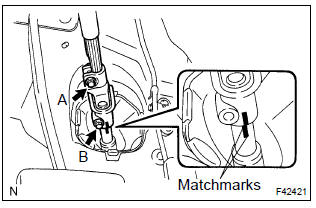
- Place matchmarks on the sliding yoke and steering intermediate shaft.
- loosen the bolt a and remove the bolt b, then disconnect the steering intermediate shaft.
13. Remove steering column assy
- Disconnect the connectors and wire harness clamps from the steering column assy.
- remove the 3 bolts and steering column assy.
14. Remove steering column upper w/switch bracket assy
- Using a centering punch, mark the center of the 2 tapered– head bolts.
- using a 3 – 4 mm (0.12 – 0.16 In.) Drill, drill into the 2 bolts.
- using a screw extractor, remove the 2 bolts and steering column upper w/switch bracket assy.
15. Remove steering column clamp upper
16. Remove ignition switch lock cylinder assy
- Place the ignition switch lock cylinder assy at the acc position.
- push down the stop pin with a screwdriver, and pull out the cylinder assy.
17. Remove un–lock warning switch assy
- Disconnect the un–lock warning switch assy connector from the ignition or starter switch assy.
- remove the un–lock warning switch assy.
18. Remove ignition or starter switch assy
- remove the 2 screws and ignition or starter switch assy from the steering column bracket assy.
19. Install ignition or starter switch assy
- install the ignition or starter switch assy to the steering column bracket assy with the 2 screws.
20. Install un–lock warning switch assy
- Install the un–lock warning switch assy.
- connect the un–lock warning switch assy connector to the ignition or starter switch assy.
21. Install ignition switch lock cylinder assy
- make sure that the ignition switch lock cylinder assy is at the acc position.
- install the ignition switch lock cylinder assy.
22. Inspect steering lock operation
- check that the steering lock mechanism is activated when removing the key.
- check that the steering lock mechanism is deactivated when inserting the key and turning it to acc position.
23. Install steering column upper w/switch bracket assy
- Temporarily install the steering column upper w/switch bracket assy and steering column upper clamp with 2 new tapered–head bolts.
- tighten the 2 tapered–head bolts until the bolt heads break off.
24. Install steering column assy
- Install the steering column assy with the 3 bolts.
Torque: 21 n·m (210 kgf·cm, 15 ft·lbf)
- connect the connectors and wire harness clamps.
25. Connect steering intermediate shaft
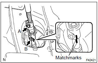
- Align the matchmarks on the sliding yoke and steering intermediate shaft.
- install the bolt b and torque the bolt a.
Torque: 35 n·m (360 kgf·cm, 26 ft·lbf)
26. Install column hole cover silencer sheet
27. Install windshield wiper switch assy
- install the windshield wiper switch assy and connect the connector.
28. Install headlamp dimmer switch assy
- install the headlamp dimmer switch assy and connect the connector.
29. Place front wheels facing straight ahead
30. Install spiral cable sub–assy
31. Connect floor shift parking lock cable assy (a/t transaxle)
- With the key in acc, push into the floor shift parking lock cable and install it.
32. Connect check key interlock operation
33. Install cover set steering column
- install the steering column cover with the 3 screws.
34. Center spiral cable
- Check that the ignition switch is at off.
- check that the battery negative terminal is disconnected.
Notice
: do not start the operation for 90 seconds after removing the terminal.
- turn the cable counterclockwise by hand until it becomes harder to turn.
- Then rotate the cable clockwise about 2.5 Turns to align the marks.
Hint
: the cable will rotate about 2.5 Turns to either right or left of the center.
35. Install steering wheel assy
- align the matchmark with the one on the steering wheel assy and steering main shaft assy.
- install the steering wheel assy with the set nut.
Torque: 50 n·m (510 kgf·cm, 37 ft·lbf)
- connect the connector.
36. Inspect horn button assy
37. Install horn button assy
Notice
:
- never use the airbag parts removed from another vehicle.
When replacing parts, replace with new ones.
- Make sure that the horn button assy is installed to the specified torque.
- If the horn button assy has been dropped, or there are cracks, dents or other defects in the case or connector, replace the horn button assy with a new one.
- When installing the horn button assy, take care so that the wirings do not interfere with other parts and that they are not pinched between other parts.
- Connect the 2 airbag connectors.
- install the horn button assy after confirming that the circumference groove of the torx screws is caught on the screw case.
- using a torx socket wrench, torque the 2 torx screws.
Torque: 8.8 N·m (90 kgf·cm, 78 in.Vlbf)
38. Steering wheel center point
39. Inspect srs warning light


Other materials:
Temporarily engaged gear steps selection mode in the D position
To drive in temporary gear steps selection mode, operate the “-” and “+” paddle
shift switches. The gear steps can then be selected by operating the “-” and “+”
paddle shift switches. By selecting gear step using paddle shift switches, you can
control engine braking forces.
1 ...
Precaution
Caution:
replace the faulty parts of the seat belt systems (outer belt, inner belt,
bolts, nuts, adjustable shoulder
anchor, tether anchor hardware, sill–bar, etc.).
Seat belt systems not in use at the time of a collision should also be inspected
and replaced if found
to be damaged or wo ...
Overhaul
1. Remove speedometer drive (mtm) gear
Remove the speedometer drive (mtm) gear from the front
differential case.
2. Remove front differential ring gear
Place matchmarks on the front differential ring gear and
front differential case.
Remove the 8 bolts. Using a hamme ...