Toyota Corolla (E120): Overhaul
1. Inspect 1st gear thrust clearance
- Using a feeler gauge, measure the 1st gear thrust clearance.
Standard clearance: 0.10 – 0.40 Mm (0.0039 – 0.0157 In.)
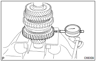
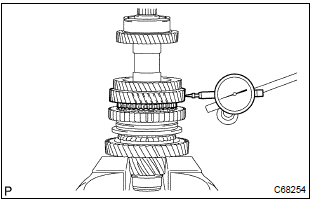
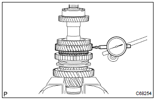
2. Inspect 2nd gear thrust clearance
- Using a dial indicator, measure the 2nd gear thrust clearance.
Standard clearance:
0.10 – 0.45 Mm (0.0039 – 0.0177 In.)
3. Inspect 1st gear radial clearance
- Using a dial indicator, measure the 1st gear radial clearance.
Standard clearance:
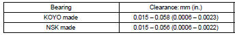
If the clearance is out of specification, replace the 1st gear needle roller bearing.
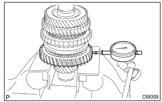
4. Inspect 2nd gear radial clearance
- Using a dial indicator, measure the 2nd gear radial clearance.
Standard clearance:
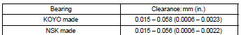
If the clearance is out of specification, replace the 2nd gear needle roller bearing.
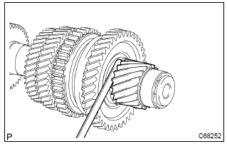
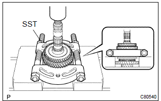
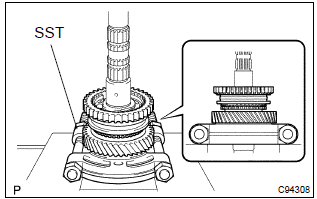
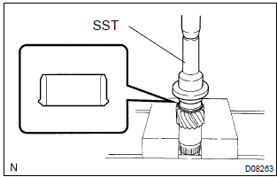
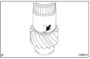
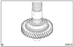
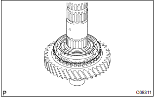
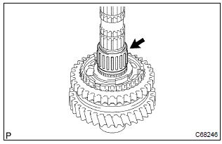
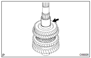
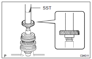
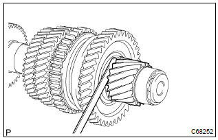
5. Remove 4th driven gear
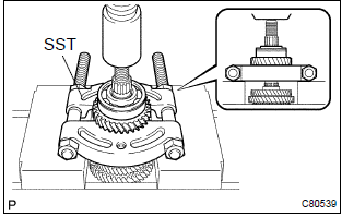
- Using sst and a press, remove the output shaft rear
bearing with 4th driven gear from the output shaft.
Sst 09950–00020
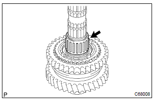
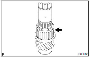
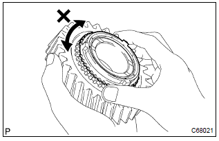
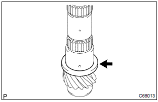
6. Remove output gear spacer
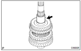
- Remove the output gear spacer from the output shaft.
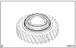
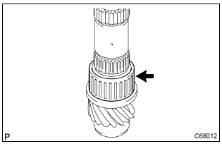
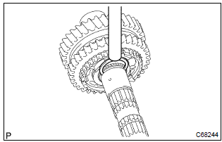
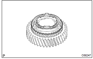
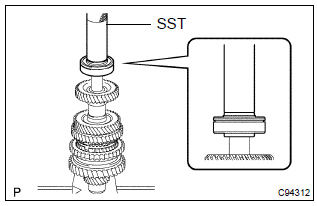
7. Remove 2nd gear
- Using sst and a press, remove the 3rd driven gear with
2nd gear from the output shaft.
Sst 09950–00020
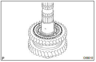
8. Remove 2nd gear needle roller bearing
- Remove the 2nd gear needle roller bearing from the output shaft.
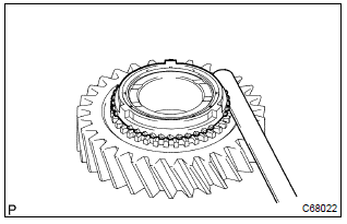
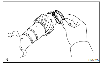
9. Remove synchronizer ring set no.2
- Remove the synchronizer ring set no.2 From the output shaft.
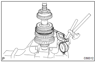
10. Remove 1st gear
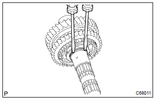
- Using 2 screwdrivers and a hammer, tap out the snap ring.
Hint
: using a waste to prevent the snap ring from being scattered.
- Using sst and a press, remove the transmission clutch
hub no.1 With 1st gear from the output shaft.
Sst 09950–00020
Notice
:
- do not tighten sst excessively.
- Support the input shaft by hand so that it will not be dropped off.
11. Remove synchronizer ring no.1
- Remove the synchronizer ring no.1 From the 1st gear.
12. Remove 1st gear needle roller bearing
- Remove the 1st gear needle roller bearing from the output shaft.
13. Remove 1st gear thrust washer
- Remove the 1st gear thrust washer from the output shaft.
14. Remove 1st gear thrust washer pin or ball
- Remove the 1st gear thrust washer pin or ball from the output shaft.
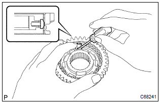
15. Remove reverse gear
- Remove the 3 synchromesh shifting keys, 3 synchromesh shifting key springs and reverse gear.
Notice
: using a waste to prevent the synchromesh shifting key and spring from being scattered.
16. Inspect output shaft
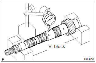
- Using a dial indicator and 2 v–blocks, measure the shaft
runout.
Maximum runout: 0.015 Mm (0.0006 In.)
If the runout exceeds the maximum, replace the output shaft.
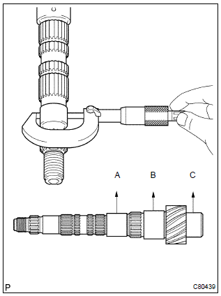
- Using a micrometer, measure the outer diameter of the
output shaft journal surface.
Outer diameter:
part a: 31.985 Mm (1.2592 In.) Part b: 37.985 Mm (1.4955 In) part c: 32.985 Mm (1.2986 In)
if the outer diameter is below the minimum, replace the output shaft.
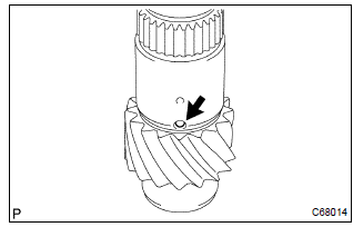
17. Inspect 2nd gear
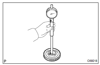
- Using a cylinder gauge, measure the inside diameter of the 2nd gear.
Inside diameter:
If the inside diameter exceeds the maximum, replace the 2nd gear.
18. Inspect 1st gear
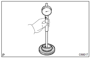
- Using a cylinder gauge, measure the inside diameter of the 1st gear.
Inside diameter:
If the inside diameter exceeds the maximum, replace the 1st gear.
19. Inspect 1st gear thrust washer
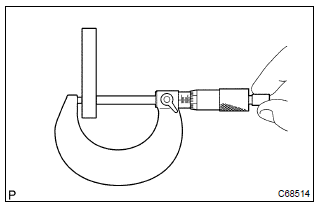
- Using a micrometer, measure the thickness of 1st gear thrust washer.
Thickness:
If the thickness is below the minimum, replace the 1st gear thrust washer.
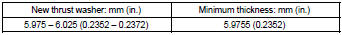
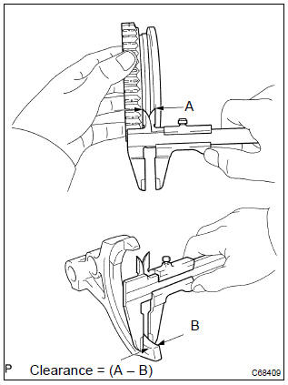
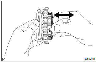
20. Inspect synchronizer ring set no.2
- Coat the 2nd gear cone with gear oil.
Check the braking effect of the synchronizer ring set no.2.
- Using a feeler gauge, measure the clearance between
the synchronizer ring back and gear spline end.
Standard clearance: 0.7 – 1.3 Mm (0.0276 – 0.0512 In.)
If the clearance is out of specification, replace the synchronizer ring set no.2.
21. Inspect synchronizer ring no.1
- Coat the 1st gear cone with gear oil.
Check the braking effect of the synchronizer ring no.1.
- Using a feeler gauge, measure the clearance between
the synchronizer ring back and gear spline end.
Standard clearance:
0.75 – 1.65 Mm (0.0295 – 0.065 In.)
If the clearance is out of specification, replace the synchronizer ring no.1.
22. Inspect reverse gear
- Using a vernier caliper gauge, measure the clearance between
reverse gear and shift fork.
Standard clearance: 0.15 – 0.35 Mm (0.0059 – 0.0138 In.)
If the clearance is out of specification, replace the reverse gear and reverse shift fork.
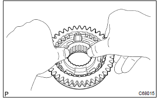
23. Inspect transmission clutch hub no.1
- Check that the transmission clutch hub no.1 And reverse gear sub–assy slides smoothly.
- check that the spline gear’s edges of the reverse gear sub–assy is not worn down.
24. Install reverse gear
- Coat the reverse gear with gear oil, install it to the transmission clutch hub no.1.
Notice
: be sure to set the reverse gear and transmission clutch hub no.1 In incorrect orientation.
- using a screwdriver, install the 3 synchromesh shifting key springs and 3 synchromesh shifting keys.
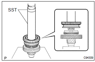
25. Install output shaft front bearing
- Using sst and a press, install the output shaft front bearing
(inner race) to the output shaft.
Sst 09223–50010
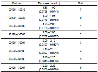
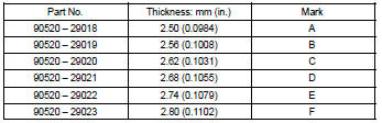
- Select a snap ring from the table below that will make the thrust clearance of the output shaft front bearing (inner race) below 0.1 Mm (0.0039 In.).
Snap ring thickness:
- Using a brass bar and a hammer, tap in the snap ring.
Notice
: take care not to damage the journal surface of the output shaft.
26. Install 1st gear thrust washer pin or ball
- Coat the 1st gear thrust washer pin or ball with mp grease, install it to the output shaft.
27. Install 1st gear thrust washer
- Coat the 1st gear thrust washer with gear oil, install it to the output shaft.
28. Install 1st gear needle roller bearing
- Coat the 1st gear needle roller bearing with gear oil, install it to the output shaft.
29. Install 1st gear
- Coat the 1st gear with gear oil, install it to the output shaft.
30. Install synchronizer ring no.1
- Coat the synchronizer ring no.1 With gear oil, install it to the 1st gear.
31. Install transmission clutch hub no.1
- Using sst and a press, install the transmission clutch
hub no.1 To the output shaft.
Sst 09316–60011 (09316–00031)
Notice
: the 1st gear can be turned.
- Select a snap ring from the table below that will make the thrust clearance of the transmission clutch hub no.1 Below 0.1 Mm (0.0039 In.).
Snap ring thickness:
- Using a brass bar and a hammer, install the snap ring to the output shaft.
Notice
: take care not to damage the journal surface of the output shaft.
32. Install 2nd gear needle roller bearing
- Coat the 2nd gear needle roller bearing with gear oil, install it to the output shaft.
33. Install synchronizer ring set no.2
- Coat the synchronizer ring set no.2 With gear oil, install it to the 2nd gear.
34. Install 2nd gear
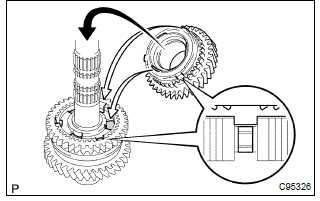
- Coat the 2nd gear with gear oil, install it to the output shaft.
Notice
: fit the synchronizer inner ring claws into the slots in the transmission clutch hub no.1.
35. Install 3rd driven gear
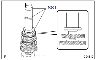
- Using sst and a press, install the 3rd driven gear to the
output shaft.
Sst 09309–36100 (09309–03610), 09608–00071, 09950–60010 (09951–00450)
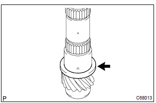
36. Install output gear spacer
- Install the output gear spacer to the output shaft.
37. Install 4th driven gear
- Using sst and a press, install 4th driven gear to the output
shaft.
Sst 09612–22011
38. Install output shaft rear bearing
- Using sst and a press, install output shaft rear bearing
to the output shaft.
Sst 09612–22011
39. Inspect 2nd gear radial clearance
- Using a dial indicator, measure the 2nd gear radial clearance.
Standard clearance:
If the clearance is out of specification, replace the 2nd gear needle roller bearing.
40. Inspect 1st gear radial clearance
- Using a dial indicator, measure the 1st gear radial clearance.
Standard clearance:
If the clearance is out of specification, replace the 1st gear needle roller bearing.
41. Inspect 2nd gear thrust clearance
- Using a dial indicator, measure the 2nd gear thrust clearance.
Standard clearance:
0.10 – 0.45 Mm (0.0039 – 0.0177 In.)
42. Inspect 1st gear thrust clearance
- Using a feeler gauge, measure the 1st gear thrust clearance.
Standard clearance:
0.10 – 0.40 Mm (0.0039 – 0.0157 In.)


Other materials:
Overhaul
Hint:
overhaul the rh side by the same procedures with lh side.
1. Remove rear wheel
2. Drain brake fluid
Notice:
wash the brake fluid off immediately if it comes into contact with any painted
surface.
3. Remove rear brake drum sub–assy
Release the parking brake lever, and remove t ...
Indicators
The indicators inform the driver of the operating state of the vehicle’s various
systems.
*1: Vehicles without a smart key system:
These lights turn on when the engine switch is turned to the “ON” position to indicate
that a system check is being performed. They will turn off after the ...
Seat belt pretensioners (front seats)
The pretensioners help the seat belts to quickly restrain the occupants by retracting
the seat belts when the vehicle is subjected to certain types of severe frontal
or side collision.
The pretensioners do not activate in the event of a minor frontal impact, a minor
side impact, a rear impact ...