Toyota Corolla (E120): Overhaul
Hint
: components:
1. Drain manual transaxle oil (m/t transaxle)
torque: 39.2 Nvm (400 Kgf·cm, 29 ft·lbf)
2. Drain automatic transaxle fluid (a/t transaxle)
torque: 17.5 Nvm (178 Kgf·cm, 13 ft·lbf)
3. Remove front wheel
4. Remove engine under cover lh
5. Remove front axle hub lh nut
- Using sst and a hammer, unstake the staked part of the
hub lh nut.
Sst 09930–00010
- while applying the brakes, remove the hub lh nut.
Notice
: loosen the staked part of the nut completely, otherwise the screw of the drive shaft may be damaged.
6. Separate front stabilizer link assy lh
- Remove the nut, separate the front stabilizer link assy lh from the shock absorber assy front lh.
Hint
: if the ball joint turns together with the nut, use a hexagon wrench (6 mm) to hold the stud.
7. Separate speed sensor front lh (w/ abs)
- Remove the bolt, separate the speed sensor front lh and flexible hose from the shock absorber assy front lh.
- Remove the bolt, separate the speed sensor front lh from the steering knuckle.
8. Separate tie rod end sub–assy lh
- Remove the cotter pin and nut.
- using sst, separate the tie rod end sub–assy lh from the
steering knuckle.
Sst 09628–62011
9. Separate front suspension arm sub–assy lower no.1 Lh
- Remove a bolt and 2 nuts, separate the front suspension arm sub–assy lower no.1 Lh from the lower ball joint.
10. Separate front axle assy lh
- Using a plastic hammer, separate the front drive shaft assy lh from the front axle assy lh.
Notice
:
- be careful not to damage the boot.
- W/ abs: be careful not to damage the speed sensor rotor.
11. Remove front drive shaft assy lh
- Using sst, remove the front drive shaft assy lh.
Sst 09520–01010, 09520–24010 (09520–32040)
Notice
: be careful not to damage the dust cover and oil seal.
Hint
: in case of not being able to remove the drive shaft at the position of the illustration (a), hook the claw of sst to the position of the illustration (b), remove it.
12. Remove front drive shaft assy rh
Hint
: remove the rh side by the same procedures as the lh side.
Notice
: be careful not to damage the dust cover and oil seal.
13. Fix front axle assy lh
Notice
: the hub bearing could be damaged if it is subjected to the vehicle weight, such as when moving the vehicle with the drive shaft removed.
Therefore, make sure to support the hub bearing with sst when the vehicle weight is applied.
Sst 09608–16042 (09608–02021, 09608–02041)
14. Inspect front drive shaft assy lh
- Check that there is no remarkable play in the outboard joint.
- check that the inboard joint slides smoothly in the thrust direction.
- check that there is no remarkable play in the radial direction of the inboard joint.
- check the boots for damage.
Notice
: keep the drive shaft assy level during inspection.
15. Remove front axle inboard joint boot lh no.2 Clamp
- Using a needle nose pliers, remove the inboard joint boot lh no.2 Clamp as shown in the illustration.
16. Remove front axle inboard joint boot lh clamp
- using a side cutter, cut the inboard joint boot lh clamp, then remove it.
17. Separate inboard joint boo
t
- separate the inboard joint boot from the inboard joint sub–assy lh.
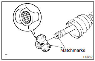
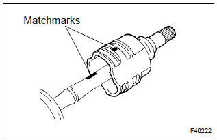
18. Remove front axle inboard joint sub–assy lh
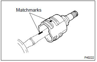
- Remove the old grease from the inboard joint sub–assy lh.
- place matchmarks on the inboard joint sub–assy lh and outboard joint shaft assy.
Notice
: do not punch the marks.
- Remove the inboard joint sub–assy lh from the outboard joint shaft assy.
- using a snap ring expander, remove the inner lh shaft snap ring.
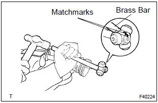
- Place matchmarks on the outboard joint shaft assy and
tripod joint assy.
Notice
: do not punch the marks.
- using a brass bar and a hammer, remove the tripod joint
assy from the outboard joint shaft assy.
Notice
: do not tap the roller.
- Using a snap ring expander, remove the inner lh shaft snap ring.
- remove the inboard joint boot lh no.2 Clamp, inboard joint boot and inboard joint boot lh clamp.
19. Remove drive shaft damper (rh drive shaft)
- using a side cutter, cut the drive shaft damper setting clamp, then remove it.
- remove the drive shaft damper.
20. Remove front drive shaft lh hole snap ring
- Using a screwdriver, remove the lh hole snap ring.
21. Remove front drive shaft dust cover lh
- Using sst and a press, remove the dust cover lh.
Sst 09950–00020
22. Install front drive shaft dust cover lh
- Using sst and a press, install a new dust cover lh, as
shown in the illustration.
Sst 09527–10011
Notice
:
- dust cover should be installed completely.
- Be careful not to damage the dust cover.
23. Install front drive shaft lh hole snap ring
- install a new lh hole snap ring.
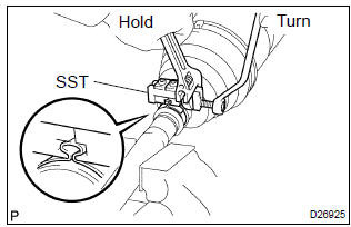
24. Install drive shaft damper (rh drive shaft)
- Set the distance, as described below.

- Through the damper setting clamp to the shaft.
- Mount drive shaft in a soft vise.
- secure the damper setting clamp onto the damper.
- place sst onto the damper setting clamp.
Sst 09521–24010
- tighten the sst so that the clamp is pinched.
Notice
: do not overtighten the sst.
- Using sst, adjust the clearance of the damper setting
clamp.
Sst 09240–00020 (09242–00150) clearance: 1.5 Mm (0.059 In.) Or less
25. Install front axle inboard joint sub–assy lh
H
int
: before installing the boot, wrap the spline of the drive shaft with vinyl tape to prevent the boot from being damaged.
- install new parts to the outboard joint shaft assy in the following order.
- Inboard joint boot lh clamp
- inboard joint boot
- inboard joint boot lh no.2 Clamp
- Using a snap ring expander, install a new inner lh shaft snap ring.
- Align the matchmarks, install tripod joint assy to the outboard joint assy.
- using a brass bar and a hammer, install the tripod joint assy.
Notice
: do not tap the roller.
- Using a snap ring expander, install a new inner lh shaft snap ring.
- pack the inboard joint sub–assy lh with grease.
Grease capacity: 135 – 155 g (4.8 – 5.5 Oz.)
- Align the matchmarks, install the inboard joint sub–assy lh to the outboard joint shaft assy.
26. Install inboard joint boot
- install the inboard joint boot to the inboard joint assy and outboard joint shaft assy.
27. Install front axle inboard joint boot lh clamp
- Mount drive shaft in a soft vise.
- secure the clamp onto the boot.
- place sst onto the clamp.
Sst 09521–24010
- tighten the sst so that the clamp is pinched.
Notice
: do not overtighten the sst.
- Using sst, adjust the clearance of the clamp.
Sst 09240–00020 (09242–00150) clearance: 1.5 Mm (0.059 In.) Or less.
28. Install front axle inboard joint boot lh no.2 Clamp
- Using a needle nose pliers, install the inboard joint boot lh no.2 Clamp as shown in the illustration.
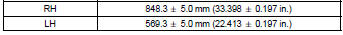
29. Inspect front drive shaft assy lh
- Check that there is no remarkable play in the outboard joint.
- check that the inboard joint slides smoothly in the thrust direction.
- check that there is no remarkable play in the radial direction of the inboard joint.
- check the boots for damage.
Notice
: keep the drive shaft assy level during inspection.
Hint
: for dimension (a), refer to the following table.
30. Install front drive shaft assy lh
- A/t: coat the spline of the inboard joint shaft assy with atf.
- m/t: coat the spline of the inboard joint shaft assy with gear oil.
- align the shaft splines, install the drive shaft assy with a brass bar and a hammer.
Notice
:
- set the hole snap ring with opening side facing downwards.
- Be careful not to damage the oil seal.
Hint
: whether the inboard joint shaft is in contact with the pinion shaft or not can be known from the sound or feeling when driving it in.
31. Install front drive shaft assy rh
H
int
: install the rh side by the same procedure as the lh side.
Notice
: do not damage the oil seal.
32. Install front axle assy lh
- install the drive shaft assy lh to the front axle assy lh.
Notice
:
- be careful not to damage the outboard joint boot.
- W/ abs: be careful not to damage the speed sensor rotor.
33. Install front suspension arm sub–assy lower no.1 Lh
- Install the lower ball joint to the front suspension arm sub–
assy lower no.1 Lh with a bolt and 2 nuts.
Torque: 89 nvm (908 Kgf·cm, 66 ft·lbf)
34. Install tie rod end sub–assy lh
- install the tie rod end sub–assy lh to the steering knuckle with
the nut.
Torque: 49 nvm (500 Kgf·cm, 36 ft·lbf)
- install a new cotter pin.
Notice
: if the holes for the cotter pin are not aligned, tighten the nut further to 60 .
35. Install speed sensor front lh (w/ abs)
- Install the speed sensor front lh and flexible hose to
shock absorber assy front lh with the bolt.
Torque: 29 nvm (296 Kgf·cm, 21 ft·lbf)
- Install the speed sensor front lh to the steering knuckle
with the bolt.
Torque: 8.0 Nvm (82 Kgf·cm, 71 ft·lbf)
Notice
:
- be careful not to damage the speed sensor.
- Keep the speed sensor clean.
- Do not twist the sensor wire when installing the sensor.
36. Install front stabilizer link assy lh
- Install the front stabilizer link assy lh with the nut.
Torque: 74 nvm (755 Kgf·cm, 55 ft·lbf)
Hint
: if the ball joint turns together with the nut, use a hexagon wrench (6 mm) to hold the stud.
37. Install front axle hub lh nut
- Install a new hub lh nut.
Torque: 216 nvm (2,200 Kgf·cm, 159 ft·lbf)
- using a chisel and a hammer, stake the hub lh nut.
38. Install front wheel
torque: 103 nvm (1,050 Kgf·cm, 76 ft·lbf)
39. Add manual transaxle oil (m/t transaxle)
40. Inspect and adjust manual transaxle oil (m/t transaxle)
41. Add automatic transaxle fluid (a/t transaxle)
42. Inspect and adjust automatic transaxle fluid (a/t transaxle)
43. Inspect and adjust front wheel alignment
44. Check abs speed sensor signal (w/ abs)


Other materials:
Inspection procedure
1 Inspect dlc3 terminal voltage(tc terminal)
Turn the ignition switch to on.
measure voltage between terminals tc and cg of dlc3.
Ok:
voltage: 10 – 14 v
2 Check harness and connector(dlc3 – body ground)
Check for open and short circuit in harness and connector betw ...
Inspection procedure
Hint:
read freeze frame data using the hand-held tester or the obd ii scan tool.
Freeze frame data records the
engine conditions when a malfunction is detected. When troubleshooting, it is
useful for determining whether
the vehicle was running or stopped, the engine was warmed up or not, the ...
Replacement
1. Remove proportioning valve assy
Using sst, disconnect the 5 brake tubes from the proportioning
valve assy.
Sst 09023–00100
Remove the 2 bolts and proportioning valve assy from the
body.
2. Install proportioning valve assy
Install the proportioning valve assy w ...