Toyota Corolla (E120): Overhaul
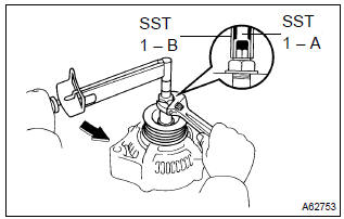
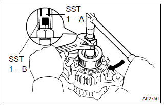
1. Remove generator pulley
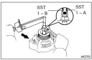
Sst 09820–63010 (09820–06010, 09820–06020)
Hint:

- Hold sst 1 – a with a torque wrench, and tighten sst 1
– b clockwise to the specified torque.
Torque: 39 nvm (398 Kgf·cm, 29 ft·lbf)
Notice
: check that sst is secured to the rotor shaft.
- Mount sst 2 in a vise.
- insert sst 1 – a, b into sst 2, and attach the pulley nut to sst 2.
- To loosen the pulley nut, turn sst 1 – a in the direction
shown in the illustration.
Notice
: to prevent damage to the rotor shaft, do not loosen the pulley nut more than one–half of a turn.
- remove the alternator form sst 2.
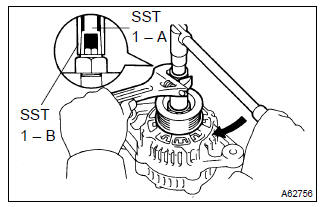
- Turn sst 1 – b, and remove sst 1 – a, b.
- remove the pulley nut and pulley.
2. Remove generator brush holder assy
- remove the nut and terminal insulator.
- remove the screw, nut and terminal plate.
- remove the 2 nuts and rear end cover.
- remove the brush cover from the brush holder.
- remove the 2 screw and brush holder.
- remove the plate seal.
3. Remove generator regulator assy
- remove the 3 screws and regulator.
4. Remove generator holder w/rectifier
- remove the 4 screws and holder w/ rectifier.
5. Remove generator rectifier end frame
- Remove the plate seal from the rectifier end frame.
- remove the 4 terminal insulator, 4 nuts and cord clip.
- using sst, remove the rectifier end frame.
Sst 09286–46011
6. Remove generator rotor assy
- remove the washer from the rotor.
- remove the rotor from drive end frame.
7. Inspect generator regulator assy
- Using an ohmmeter, check the continuity between terminals f and b.
Standard
: when the positive and negative poles between terminals f and b are exchanged, there is continuity in one way but no continuity in another way.
- Using an ohmmeter, check the continuity between terminals f and e.
Standard
: when the positive and negative poles between terminals f and e are exchanged, there is continuity in one way but no continuity in another way.
8. Inspect generator regulator assy
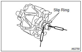
- Using an ohmmeter, check that there is continuity between
the slip rings.
Standard resistance: 2.1 – 2.5 W at 20 c (68 f)
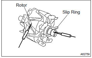
- Using an ohmmeter, check that there is no continuity between the slip ring and rotor.
- Using a vernier calipers, measure the slip ring diameter.
Standard diameter: 14.2 – 14.4 Mm (0.559 – 0.567 In.) Minimum diameter: 12.8 Mm (0.504 In.)
9. Inspect brush
- Using a vernier calipers, measure the exposed brush
length.
Standard exposed length: 9.5 – 11.5 Mm (0.374 – 0.453 In.) Minimum exposed length: 1.5 Mm (0.059 In.)
10. Install generator rotor assy
- Install the rotor to the drive end frame.
- install the washer on the rotor.
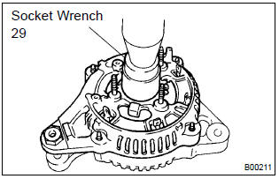
- Using a socket wrench 29 and press, slowly press in the rectifier end frame.
- Install the cord clip and 4 nuts.
Torque:
nut a 4.5 Nvm (46 Kgf·cm, 40 in.Vlbf) nut b 5.4 Nvm (55 Kgf·cm, 48 in.Vlbf)
11. Install generator holder w/rectifier
- install the holder w/ rectifier with 4 screws.
Torque: 2.9 Nvm (30 Kgf·cm, 26 in.Vlbf)
12. Install generator regulator assy
- install the regulator with the 3 screw.
Torque: 2.0 Nvm (20 Kgf·cm, 18 in.Vlbf)
13. Install generator brush holder assy
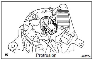
- Place the plate seal on the brush holder.
- install the brush holder with the 2 screws.
Torque: 2.0 Nvm (20 Kgf·cm, 18 in.Vlbf)
Notice
: pay attention to the holder installation direction.
- place the brush cover on the brush holder.
- install the rear end cover with the 2 nuts.
Torque: 4.4 Nvm (45 Kgf·cm, 39 in.Vlbf)
- install the terminal plate with the screw and nut.
Torque:
bolt 3.9 Nvm (40 Kgf·cm, 35 in.Vlbf) nut 4.4 Nvm (45 Kgf·cm, 39 in.Vlbf) - install the terminal insulator withe the nut.
Torque: 4.1 Nvm (42 Kgf·cm, 36 in.Vlbf)
14. Install generator pulley
Sst 09820–63010 (09820–06010, 09820–06020)
Hint:
- Install the pulley to the rotor shaft by tightening the pulley nut by hand.
- hold sst 1 – a with a torque wrench, and tighten sst 1
– b clockwise to the specified torque.
Torque: 39 nvm (398 Kgf·cm, 29 ft·lbf)
Notice
: check that sst is secured to the pulley shaft.
- Mount sst 2 in a vise.
- insert sst 1 – a, b into sst 2, and attach the pulley nut to sst 2.
- Tighten the pulley nut, turn sst 1 – a in the direction
shown in the illustration.
Torque: 111 nvm (1,132 Kgf·cm, 82 ft·lbf)
- remove the alternator form sst 2.
- Turn sst 1 – b, and remove sst 1 – a, b.
- turn the pulley, and check that the pulley moves smoothly.


Other materials:
Engine assembly
Inspection
1. Inspect coolant
2. Inspect engine oil
3. Inspect battery
4. Inspect air cleaner filter element sub–assy
5. Inspect spark plug
6. Inspect fan and generator v belt
Hint:
you don’t need to check the belt deflection because auto tensioner is adopted.
7. Inspect ignition ti ...
Replacement
1. Remove hood sub–assy
2. Remove cylinder head cover no.2
3. Remove battery
4. Remove battery carrier
Remove the 4 bolts and battery carrier.
5. Remove air cleaner assembly with hose
6. Remove floor shift cable transmission control shift
Remove the nut from the control shaf ...
Warning lights and indicators
The warning lights and indicators on the instrument cluster and center panel
inform the driver of the status of the vehicle’s various systems.
For the purpose of explanation, the following illustration displays all warning
lights and indicators illuminated.
► Vehicles with a drive moni ...