Toyota Corolla (E120) 2002–2008 Repair Manual / Diagnostics / Toyota vehicle intrusion protection system / Ignition switch circuit / Inspection procedure
Toyota Corolla (E120): Inspection procedure
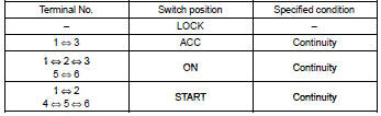
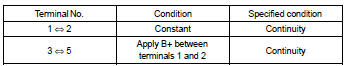
1 Check ignition or starter switch assy
- Check the ignition switch, as shown in the illustration and table.
Standard:

2 Check fuse (ecu–b)
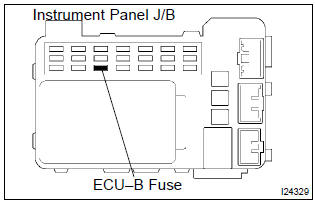
- Remove the fuse from the instrument panel j/b.
- check the continuity of the fuse.
Standard: continuity


3 Check relay (marking: ig1)
- Remove the relay from the instrument j/b.
- inspect the relay continuity, as shown in the illustration and table.
Standard:


4 Check tvip ecu
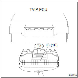
- Disconnect the tvip ecu connector.
- turn the ignition switch on.
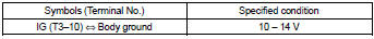
- measure the voltage between the terminal of the ecu connector and the body ground, as shown in the illustration and table.
Standard:

Check and replace tvip ecu


Other materials:
Calling the message sender
Calls can be made to an e-mail/SMS/MMS message sender's phone number.
1 Display the “Message Inbox” screen.
2 Select the desired message.
3 Select .
4 Check that the “Call” screen is displayed.
■ Calling from a number within a message
Calls can be made to a number identified ...
Transmission valve body assy (atm)
Replacement
1. Remove engine under cover lh
2. Drain automatic transaxle fluid
remove the drain plug, gasket and drain atf.
install a new gasket and drain plug.
Torque: 17.5 Nvm (178 Kgf·cm, 13 ft·lbf)
3. Remove automatic transaxle oil pan sub–assy
Remove the 18 ...
Wiper & washer
Preparation
Sst
Recomended tools
Equipment
...