Toyota Corolla (E120) 2002–2008 Repair Manual / Diagnostics / Supplemental restraint system / Short in d squib circuit (to b+) / Inspection procedure
Toyota Corolla (E120): Inspection procedure
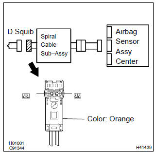
1 Check d squib circuit(airbag sensor assy center – horn button assy)
- Disconnect the negative (–) terminal cable from the battery, and wait at least for 90 seconds.
- disconnect the connectors between the airbag sensor assy center and the horn button assy.
- connect the negative (–) terminal cable to the battery, and wait at least for 2 seconds.
- turn the ignition switch to on.
- for the orange connector (on the spiral cable sub–assy
side) between the horn button assy and the spiral cable
sub–assy, measure the voltage between d+ and body
ground.
Ok: voltage: below 1 v


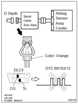
2 Check air bag sensor assy center
- Turn the ignition switch to lock.
- disconnect the negative (–) terminal cable from the battery, and wait at least for 90 seconds.
- connect the connector to the airbag sensor assy center.
- using a service wire, connect d+ and d– of the orange connector (on the spiral cable sub–assy side) between the horn button assy and the spiral cable sub–assy.
- connect the negative (–) terminal cable to the battery, and wait at least for 2 seconds.
- turn the ignition switch to on, and wait at least for 20 seconds.
- clear the dtc stored in memory .
- turn the ignition switch to lock, and wait at least for 20 seconds.
- turn the ignition switch to on, and wait at least for 60 seconds.
- check the dtc .
Ok: dtc b0103/12 is not output.
Hint
: codes other than code b0103/12 may be output at this time, but they are not relevant to this check.


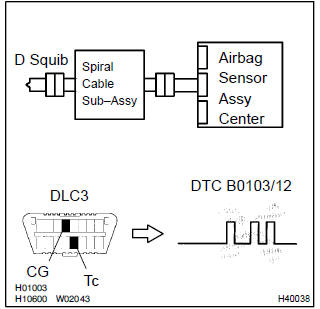
3 Check d squib
Sst 09843–18040
- Turn the ignition switch to lock.
- disconnect the negative (–) terminal cable from the battery, and wait at least for 90 seconds.
- connect the horn button assy connectors.
- connect the negative (–) terminal cable to the battery, and wait at least for 2 seconds.
- turn the ignition switch to on, and wait at least for 20 seconds.
- clear the dtc stored in memory .
- turn the ignition switch to lock, and wait at least for 20 seconds.
- turn the ignition switch to on, and wait at least for 20 seconds.
- check the dtc .
Ok: dtc b0103/12 is not output.
Hint
: codes other than code b0103/12 may be output at this time, but they are not relevant to this check.


4 Use simulation method to check


Replace all srs components including the wire harness
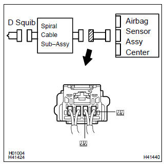
5 Check instrument panel wire(airbag sensor assy center – spiral cable sub–assy)
- Turn the ignition switch to lock.
- disconnect the connectors of the instrument panel wire.
- turn the ignition switch to on.
- for the connector (on the spiral cable sub–assy side) between
the airbag sensor assy center and the spiral cable
sub–assy, measure the voltage between d+ and body
ground.
Ok: voltage: below 1 v

6 Check spiral cable sub–assy
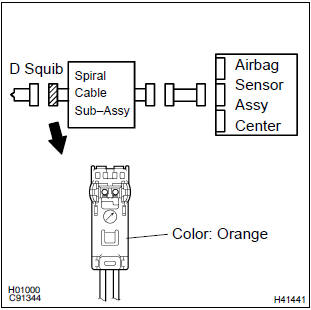
- For the orange connector (on the spiral cable sub–assy
side) between the horn button assy and the spiral cable
sub–assy, measure the voltage between d+ and body
ground.
Ok: voltage: below 1 v

7 Use simulation method to check


Replace all srs components including the wire harness


Other materials:
Inspection procedure
1 Inspect transmission wire(s1)
Disconnect the transmission wire connector from the
transaxle.
measure the resistance according to the value(s) in the
table below.
Standard:
2 Check harness and connector(transmission wire – ecm)
Connect the transmission connec ...
Inspection
1. Inspect front seat inner belt assy lh
When fastening the seat belt (buckle switch on).
Inspect the continuity and resistance between the
terminals.
Standard:
If the result is not as specified, replace the inner belt.
When releasing the seat belt (buckle switch ...
Replacement
Hint: components:
1. Table of bolt, screw and nut
Notice:
be sure to tape the tip of the screwdriver when using it to disengage the
meshing of the clips and
claws.
Hint:
indicate the bolts, screws and nuts, which are necessary for installation and
removal of the instrument panel,
in th ...