Toyota Corolla (E120): Inspection
1. Windshield wiper switch assy
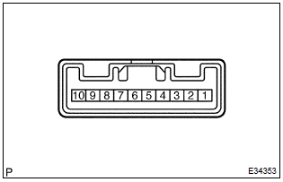
- Continuity check
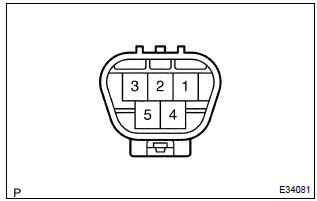
- check the continuity of each terminal of the connector.
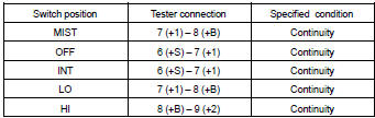
Front wiper switch
Standard:
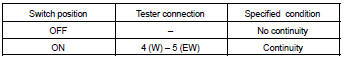
Front washer switch
Standard:
- W/o intermittent time adjust: intermittent operation check
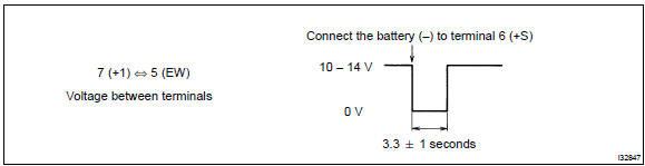
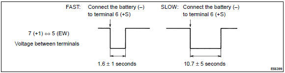
- connect the voltmeter (+) terminal to terminal 7 (+1) of the connector, the voltmeter (–) terminal to terminal 5 (ew) of the connector.
- Connect the battery (+) to terminal 8 (+b) of the connector, the battery (–) to terminal 5 (ew) and 6 (+s) of the connector.
- Turn the wiper switch to the int position.
- Connect the battery (+) to terminal 6 (+s) of the connector for 5 seconds.
- Connect the battery (–) to terminal 6 (+s) of the connector.
Operate the intermittent wiper relay and check voltage between terminal 7 (+1) and terminal 5 (ew).
- W/ intermittent time adjust: intermittent operation check
- connect the voltmeter (+) terminal to terminal 7 (+1) of the connector, the voltmeter (–) terminal to terminal 5 (ew) of the connector.
- Connect the battery (+) to terminal 8 (+b) of the connector, the battery (–) to terminal 5 (ew) and 6 (+s) of the connector.
- Turn the wiper switch to the int position.
- Connect the battery (+) to terminal 6 (+s) of the connector for 5 seconds.
- Connect the battery (–) to terminal 6 (+s) of the connector.
Operate the intermittent wiper relay and check voltage between terminal 7 (+1) and terminal 5 (ew).
- Operation check (washer switch)
- turn the wiper switch to the off position.
- Connect the battery (+) to terminal 8 (+b) of the connector, the battery (–) to terminal 6 (+s) and 5 (ew) of the connecter.
- Connect the voltmeter (+) terminal to terminal 7 (+1)
of the connector, the voltmeter (–) terminal to terminal
5 (ew) of the connector. Turn the washer switch
to on and off and check voltage between terminal
7 (+1) and terminal 5 (ew).
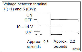
Standard: see the illustration.
2. Windshield wiper motor assy
- Lo operation check
- connect the battery (+) to terminal 1 (+1) of the connector, the battery (–) to terminal 5 (e) of the connector, and check that the motor operates at low speed (lo).
- hi operation check
- connect the battery (+) to terminal 4 (+2) of the connector, the battery (–) to terminal 5 (e) of the connector, and check that the motor operates at high speed (hi).
- automatic stop operation check
- connect the battery (+) to terminal 1 (+1) of the connector,
the battery (–) to terminal 5 (e) of the connector.
With the motor being rotated at low speed (lo), disconnect terminal 1 (+1) to stop the wiper motor operation at any position except the automatic stop position.
- Connect terminal 1 (+1) and 3 (s), and the battery
(+) to terminal 2 (b) to restart the motor operation at
low speed.
Sst 09843–18040
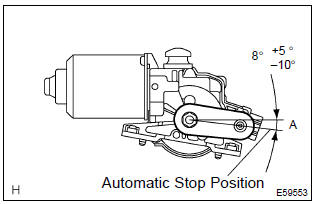
- Check that the automatic stop position is correct.
Standard: see the illustration.


Other materials:
Bluetooth® (Multimedia system)
Bluetooth®
■When using the Bluetooth® audio system
●In the following conditions, the system may not function.
• If the portable audio player is turned off
• If the portable audio player is not connected
• If the portable audio player’s battery is low
●There may be a ...
Uniform Tire Quality Grading
This information has been prepared in accordance with regulations issued by the
National Highway Traffic Safety Administration of the U.S. Department of Transportation.
It provides the purchasers and/or prospective purchasers of Toyota vehicles with
information on uniform tire quality grading.
...
Transmission wire (atm)
Replacement
1. Remove transmission valve body assy
2. Remove transmission wire
Disconnect the transmission wire connector.
removal the bolt and transmission wire.
3. Install transmission wire
Coat a o–ring with atf.
install the transmission wire and bolt.
To ...