Toyota Corolla (E140) 2007–2013 Body Repair Manual / Body dimensions / General information
Toyota Corolla (E140): General information
1. Basic dimensions
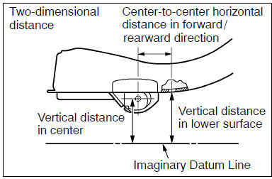
(a) there are two types of dimensions in the diagram.
(1) (Three-dimensional distance)
- straight-line distance between the centers of two measuring points.
(2) (Two-dimensional distance)
- horizontal distance in forward/rearward direction between the centers of two measuring points.
- The height from an imaginary datum line.
(B) in cases in which only one dimension is given, left and right are symmetrical.
(C) the dimensions in the following drawing indicate actual distance.
Therefore, please use the dimensions as a reference.
(D) the line that connects the places listed below is the imaginary datum line when measuring the height. (The dimensions are printed in the text.)
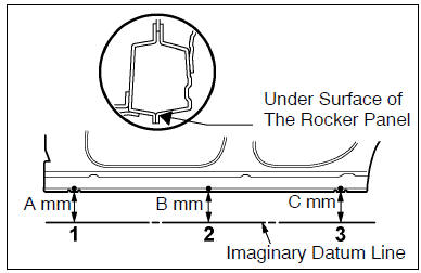
| Symbol | Name |
| 1 | The place that was lowered a mm from the under surface of the rocker panel centered on the front jack up point. |
| 2 | The place that was lowered b mm from the under surface of the rocker panel centered between 1 and 3. |
| 3 | The place that was lowered c mm from the under surface of the rocker panel centered on the rear jack up point. |
2. Measuring
(a) basically, all measurements are to be done with a tracking gauge. For portions where it is not possible to use a tracking gauge, a tape measure should be used.
(B) use only a tracking gauge that has no looseness in the body, measuring plate, or pointers.
Hint:
- the height of the left and right pointers must be equal.
- Always calibrate the tracking gauge before measuring or after adjusting the pointer height.
- Take care not to drop the tracking gauge or otherwise shock it.
- Confirm that the pointers are securely in the holes.
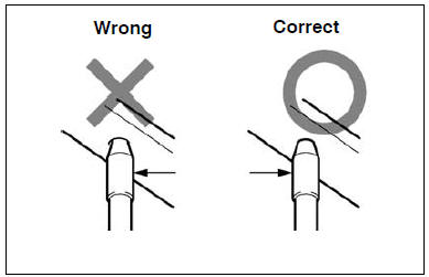
(C) when using a tape measure, avoid twists and bends in the tape.


Other materials:
Inspection procedure
Hint:
read freeze frame data using the hand-held tester or the obd ii scan tool.
Freeze frame data records the
engine conditions when a malfunction is detected. When troubleshooting, it is
useful for determining whether
the vehicle was running or stopped, the engine was warmed up or not, the ...
Front differential oil seal (atm)
Replacement
1. Remove front wheels
2. Remove engine under cover rh
3. Remove engine under cover lh
4. Drain automatic transaxle fluid
remove the drain plug, gasket and drain atf.
install a new gasket and drain plug.
Torque: 17.5 Nvm (178 Kgf·cm, 13 ft·lbf)
5. Remove fron ...
Replacement
Hint:
for parking brake cable assy no.2, Perform the same procedure to the parking
brake cable assy no.3.
1. Remove rear wheel
2. Remove rear brake drum sub–assy
3. Remove rear brake automatic adjust lever lh
4. Remove front brake shoe
sst 09718–00010
5. Remove parking brake sho ...