Toyota Corolla (E120) 2002–2008 Repair Manual / Front suspension / Front wheel alignment
Toyota Corolla (E120): Front wheel alignment
Adjustment
1. Inspect tire
2. Measure vehicle height
Vehicle height:
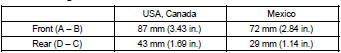
Measuring points:
a: ground clearance of front wheel center
b: ground clearance of lower suspension arm front
bolt center
c: ground clearance of axle beam set bolt center
d: ground clearance of rear wheel center
Notice
: before inspecting the wheel alignment, adjust the vehicle height to the specified value. If the vehicle height is not the specified value, try to adjust it by pushing down on or lifting the body.
3. Inspect toe–in
Toe–in:

If the toe–in is not within the specified value, adjust it at the rack ends.
4. Adjust toe–in
- remove the rack boot set clips.
- loosen the tie rod end lock nuts.
- turn the right and left rack ends by an equal amount to adjust the toe–in.
Hint
: try to adjust the toe–in to the center of the specified value.
- Make sure that the lengths of the right and left rack ends
are the same.
Rack end length difference: 1.5 Mm (0.059 In.) Or less
- torque the tie rod end lock nuts.
Torque: 74 n·m (755 kgf·cm, 55 ft·lbf)
- place the boots on the seats and install the clips.
Hint
: make sure that the boots are not twisted.
5. Inspect wheel angle
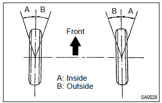
- Turn the steering wheel fully and measure the turning angle.
Wheel turning angle:
If the right and left inside wheel angles differ from the specified value, check the right and left rack end lengths.
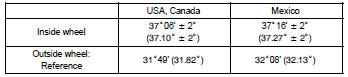
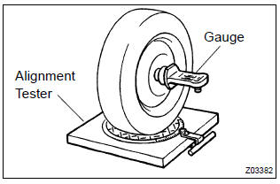
6. Inspect camber, caster and steering axis inclination
- Install the camber–caster–kingpin gauge or position vehicle on wheel alignment tester.
- inspect the camber, caster and steering axis inclination.
Camber, caster and steering axis inclination:
If the caster and steering axis inclination are not within the specified values, after the camber has been correctly adjusted, recheck the suspension parts for damaged and/or worn out parts.
7. Adjust camber
Notice
: after the camber has been adjusted, inspect the toe–in.
- remove the front wheel.
- Remove the 2 nuts on the lower side of the shock absorber
assy front lh.
Notice
: when removing nut, stop the bolt from rotating and loosen the nut.
- clean the installation surfaces of the shock absorber assy front lh and the steering knuckle.
- temporarily install the 2 nuts.
- Adjust the camber by pushing or pulling the lower side of the shock absorber in the direction in which the camber adjustment is required.
- tighten the nuts.
Torque: 153 nvm (1,560 Kgf·cm, 113 ft·lbf)
- install the front wheel.
Torque: 103 n·m (1,050 kgf·cm, 76 ft·lbf)
- Check the camber.
Hint
:
- try to adjust the camber to the center of the specified value.
- Adjusting value for the set bolts is –1 30’ – 0 30’ (–1.5 – 0.5 ).
If the camber is not within the specified value, using the following table, estimate how much additional camber adjustment will be required, and select the camber adjusting bolt.
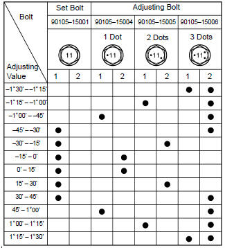
- Perform the steps mentioned above again. At step (e), replace 1 or 2 selected bolts.
Hint
: when replacing the 2 bolts, replace 1 bolt at a time.


Other materials:
Inspection procedure
1 Inspect shift solenoid valve(sl)
Remove the shift solenoid valve sl.
measure the resistance according to the value(s) in the
table below.
Standard:
Connect the positive (+) battery lead to the solenoid connector
terminal, and the negative (–) battery lead to the
so ...
Driving
► Automatic transmission or continuously
variable transmission
1 With the brake pedal depressed, shift the shift lever to D.
(, 174, 176)
2 Release the parking brake.
3 Gradually release the brake pedal and gently depress the accelerator pedal to
accelerate the vehicle.
► ...
Circuit description
If the engine coolant temperature (ect) does not reach 75°c (167°f) despite
sufficient warm – up time has
elapsed.
Dtc no
Dtc detection condition
Trouble area
P0128
Condition (a), (b) and (c):
cold start
after engine is warmed up
& ...