Toyota Corolla (E120) 2002–2008 Repair Manual / Front suspension / Front suspension arm sub–assy lower no.1 Lh
Toyota Corolla (E120): Front suspension arm sub–assy lower no.1 Lh
Replacement
Hint
: components:
1. Remove front wheel
2. Disconnect front stabilizer link assy lh (lh (a/t) position)
3. Disconnect front stabilizer link assy rh (lh (a/t) position)
Hint
: remove the rh side by the same procedures as the lh side.
4. Separate front suspension arm sub–assy lower no.1 Lh
- Remove the bolt and 2 nuts, and separate the front suspension arm sub–assy lower no.1 Lh from the lower ball joint assy front lh.
5. Separate front suspension arm sub–assy lower no.1 Rh (lh (a/t) position)
Hint
: remove the rh side by the same procedures as the lh side.
6. Separate rack & pinion power steering gear assy (lh (a/t) position)
- remove the 4 bolts, separate the rack & pinion power steering gear
assy.
Notice
: loosen the bolt since the nut cannot be rotated.
- suspend the rack & pinion power steering gear assy.
7. Suspend engine assy (lh (a/t) position)
8. Separate front suspension crossmember sub–assy (lh (a/t) position)
- Remove the 3 bolts and 3 nuts, disconnect the transverse engine engine mounting insulator and engine mounting member sub–assy center from the front suspension crossmember sub–assy.
- Remove the 4 bolts.
- lower the transmission jack, remove the front suspension crossmember sub–assy.
9. Remove front suspension arm sub–assy lower no.1 Lh
- Remove the 2 bolts, nut and front suspension arm sub– assy lower no.1 Lh from the front suspension crossmember sub–assy.
10. Temporary tighten front suspension arm sub–assy lower no.1 Lh
- Install the front suspension arm sub–assy lower no. 1 Lh, temporarily tighten the 2 bolts and nut.
11. Install front suspension crossmember sub–assy (lh (a/t) position)
- lift the front suspension crossmember sub–assy up with a transmission jack.
- Insert sst to the base hole of the rh side crossmember
and rh side of the vehicle.
Sst 09670–00010
- tighten the bolt temporarily in the order a and b.
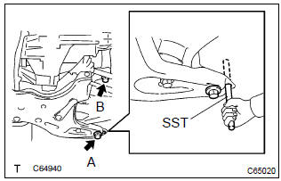
- Insert sst to the base hole of the lh side of crossmember
and lh side of the vehicle.
Sst 09670–00010
- tighten the bolt temporarily in the order a and b.
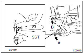
- insert sst to the base hole of the rh side of crossmember
and rh side of the vehicle.
Sst 09670–00010
- Then tighten the bolt a and b by the specified torque.
Torque:
bolt a: 157 nvm (1,601 Kgf·cm, 116 ft·lbf) bolt b: 113 nvm (1,152 Kgf·cm, 83 ft·lbf) - insert sst to the base hole of the lh side of crossmember
and lh side of the vehicle.
Sst 09670–00010
- tighten the bolt a and b by the specified torque.
Torque:
bolt a: 157 nvm (1,601 Kgf·cm, 116 ft·lbf) bolt b: 113 nvm (1,152 Kgf·cm, 83 ft·lbf)
- Connect the transverse engine engine mounting insulator and engine mounting member sub–assy center to the front suspension crossmember sub–assy.
- install the 3 bolts and 3 nuts.
Torque: 52 nvm (530 Kgf·cm, 38 ft·lbf)
12. Install rack & pinion power steering gear assy (lh (a/t) position)
- install the rack & pinion power steering gear assy with the 4
bolts.
Torque: 58 nvm (591 Kgf·cm, 43 ft·lbf)
13. Install front suspension arm sub–assy lower no.1 Lh
- Install the front suspension arm sub–assy lower no.1 Lh
with the 2 nuts and bolt to the lower ball joint assy front lh.
Torque: 89 nvm (908 Kgf·cm, 66 ft·lbf)
14. Install front suspension arm sub–assy lower no.1 Rh (lh (a/t) position)
Hint
: install the rh side by the same procedures as the lh side.
15. Install front stabilizer link assy lh (lh (a/t) position)
16. Install front stabilizer link assy rh (lh (a/t) position)
Hint
: install the rh side by the same procedure as the lh side.
17. Stabilize suspension
- install the front wheel and jack down the vehicle.
Torque: 103 nvm (1,050 Kgf·cm, 76 ft·lbf)
- bounce the vehicle up and down several times to stabilize the suspension.
18. Fully tighten front suspension arm sub–assy lower no.1 Lh
- Fully tighten the 2 bolts and nut.
Torque: 137 nvm (1,397 Kgf·cm, 101 ft·lbf)
Notice
: tighten the bolt since the nut cannot be rotated.
19. Inspect and adjust front wheel alignment


Other materials:
Types of child restraints
Child restraint systems are classified into the following 3 types according to
the age and size of the child:
► Rear facing - Infant seat/convertible seat
► Forward facing - Convertible seat
► Booster seat
■Selecting an appropriate child restraint system
●U ...
Exhaust gas precautions
Harmful substance to the
human body is included in
exhaust gases if inhaled.
WARNING
Exhaust gases include harmful
carbon monoxide (CO), which is
colorless and odorless. Observe
the following precautions.
Failure to do so may cause
exhaust gases enter the vehicle
and may lead to an accident
caused ...
Inspection procedure
1 Check d squib circuit(airbag sensor assy center – horn button
assy)
Disconnect the negative (–) terminal cable from the battery,
and wait at least for 90 seconds.
disconnect the connectors between the airbag sensor
assy center and the horn button assy.
connect the ...