Toyota Corolla (E120) 2002–2008 Repair Manual / Diagnostics / Supplemental restraint system / Tc terminal circuit / Circuit description
Toyota Corolla (E120): Circuit description
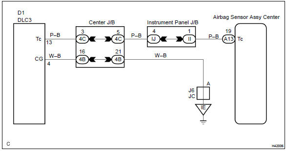
Dtc output mode is set by connecting between tc and cg of the dlc3.
The dtcs are displayed by blinking the srs warning light.
Wiring diagram
Hint
: when each warning light stays blinking, ground short in the wiring until the terminal tc of the dlc3 or internal ground short in each ecu is suspected.


Other materials:
Replacement
Hint: components:
1. Precaution
2. Disconnect battery negative terminal
3. Remove parking brake hole cover sub–assy
4. Remove floor shift shift lever knob sub–assy (m/t transaxle)
5. Remove shifting hole cover sub–assy (m/t transaxle)
6. Remove console panel upper
7. Remove conso ...
Circuit description
The seat belt buckle switch (lh) circuit consists of the airbag sensor assy
center and front seat inner belt
assy (lh).
Dtc b0126/b0127/27 is recorded when a malfunction is detected in the seat belt
buckle switch (lh) circuit.
Wiring diagram
...
Circuit description
When the ignition switch is turned on, battery positive voltage is applied to
the coilwhich closes the contacts
of the efi main relay (marked: efi) and supplies power to terminal +b of the ecm.
This signal causes current to flow to the coil, closing the contacts of the efi
relay and supplyin ...