Toyota Corolla (E120) 2002–2008 Repair Manual / Diagnostics / Sfi system / Oxygen sensor circuit no activity
detected / Circuit description
Toyota Corolla (E120): Circuit description
Refer to dtc p0130
|
Dtc no. |
Dtc detecting condition |
Trouble area |
| P0134 | After engine is warmed up, heated oxygen sensor (bank 1
sensor 1) output does not indicate rich (greater than 0.45 V)
even once when conditions (a), (b), (c), (d) and (e) continue for
more than 65 seconds (1 trip detection logic) :
|
|
Hint
: after confirming dtc p0134, check the output voltage of the heated oxygen sensor (bank 1 sensor 1) in the ”diagnosis / enhanced obd ii / data list / all” using the hand-held tester or the obd ii scan tool.
If the output voltage of the heated oxygen sensor is always less than 0.1 V, the sensor circuit may be open or short.
Monitor description
The ecm uses the heated oxygen sensor to optimize the air–fuel mixture in the closed–loop fuel control.
This control helps decrease exhaust emissions by providing the catalyst with a nearly stoichiometric mixture.
The sensor detects the oxygen level in the exhaust gas and the ecm uses this data to control the air–fuel ratio. The sensor output voltage ranges from 0 v to 1 v. If the signal voltage is less than 0.4 V, the air–fuel ratio is lean. If the signal voltage is more than 0.5 V, the air–fuel ratio is rich. If the sensor does not indicate rich even once despite the conditions for the closed–loop fuel control being met and a specified time period has passed, the ecm will conclude that the closed–loop fuel control is malfunctioning. The ecm will illuminate the mil and a dtc is set.
Monitor strategy
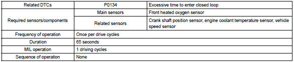
Typical enabling condition
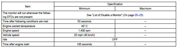
Typical malfunction thresholds

Component operating range

Wiring diagram
Refer to dtc p0130


Other materials:
Circuit description
The srs warning light is located on the combination meter.
When the srs is normal, the srs warning light lights up for approx. 6 Seconds
after the ignition switch is
turned from the lock position to on position, and then turns off automatically.
If there is a malfunction in the srs, the srs ...
Sound quality is bad only when playing tape
Inspection procedure
1 Replace cassette tape with another and recheck
Replace the cassette tape with another and recheck.
Replace the faulty cassette tape with the normal one to see if the
same trouble occurs again.
Standard: malfunction disappear.
2 Check for any foreig ...
Inspection procedure
1 Check d squib circuit(airbag sensor assy center – horn button
assy)
Disconnect the negative (–) terminal cable from the battery,
and wait at least for 90 seconds.
disconnect the connectors between the airbag sensor
assy center and the horn button assy.
release the airbag activ ...