Toyota Corolla (E120) 2002–2008 Repair Manual / Diagnostics / Sfi system / Oxygen sensor / Circuit description
Toyota Corolla (E120): Circuit description
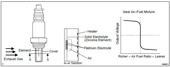
The rear heated oxygen sensor is used to monitor oxygen concentration in the exhaust gas. For optimum catalytic converter operation, the air fuel mixture must be maintained near the ideal ”stoichiometric” ratio.
The heated oxygen sensor output voltage changes suddenly in the vicinity of the stoichiometric ratio. The ecm adjusts the fuel injection time so that the air–fuel ratio is nearly stoichiometric.
When the air–fuel ratio becomes lean, the oxygen concentration in the exhaust gas increases. And the heated oxygen sensor informs the ecm of the lean condition (low voltage, i.E. Less than 0.45 V).
When the air–fuel ratio is richer than the stoichiometric air–fuel ratio, the oxygen will be vanished from the exhaust gas. And the heated oxygen sensor informs the ecm of the rich condition (high voltage, i.E.
More than 0.45 V).
|
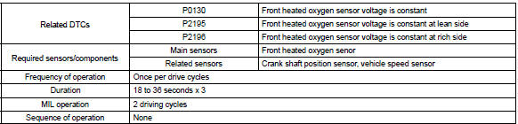
Dtc no. |
Dtc detection condition |
Trouble area |
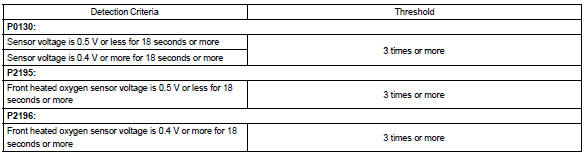
| P0130 | Output voltage of heated oxygen sensor remains at 0.4 V or more, or 0.5 V or less, during idling after engine is warmed up (2 trip detection logic) |
|
| P2195 | Output voltage of heated oxygen sensor remains at 0.5 V or less, during idling after engine is warmed up (2 trip detection logic) | |
| P2196 | Output voltage of heated oxygen sensor remains at 0.4 V or more, during idling after engine is warmed up (2 trip detection logic) |
Hint
:
- sensor 1 refers to the sensor closest to the engine assembly.
- The output voltage of the heated oxygen sensor and the short–term fuel trim value can be read using the hand–held tester or the obd ll scan tool.
Monitor description
The engine control module (ecm) uses the heated oxygen sensor information to regulate the air–fuel ratio near to the stoichiometric air–fuel ratio. The sensor detects oxygen levels in the exhaust gases and sends this signal to the ecm. This maximizes the catalytic converter’s ability to purify the exhaust gases.
The heated oxygen sensor element consists of the platinum coated zirconia and heating element. The inner surface of sensor element is exposed to the outside air, and the outer surface of sensor element is exposed to the exhaust gases. The sensor generates between 0 v and 1 v of the voltage output in response to the oxygen concentration in the exhaust gases. The sensor’s output voltage varies suddenly in the vicinity of the stoichiometric air–fuel ratio.
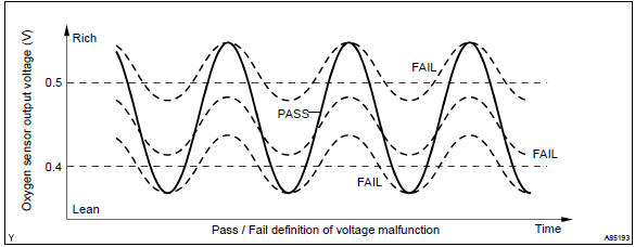
Under normal condition, the output voltage from the heated oxygen sensor alternates between rich and lean sides periodically. When it is 0.4 V or less, the air–fuel ratio is judged as lean.
If the heated oxygen sensor outputs rich signal (or lean signal) constantly, or if the heated oxygen sensor cannot output enough voltage to reach the minimum specification, the ecm interprets this as a malfunction in the heated oxygen sensor and sets a dtc.
Monitor strategy
Typical enabling condition
Typical malfunction thresholds
Component operating range

Monitor result (mode 06 data)
Refer for detailed information on checking monitor status.
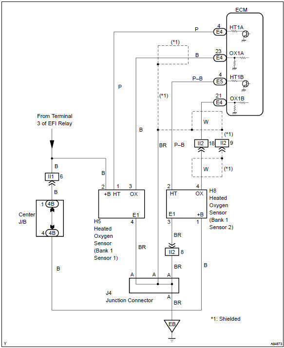
Wiring diagram
Confirmation driving pattern
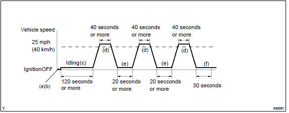
- Connect the hand–held tester to the dlc3.
- switch the hand–held tester from the ”normal mode” to the ”check mode” .
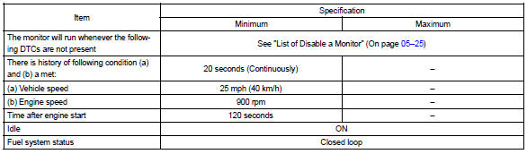
- start the engine and let the engine idle for 120 seconds or more.
- drive the vehicle at 25 mph (40 km/h) or more for 40 seconds or more.
- let the engine idle for 20 seconds or more. Perform steps (d) and (e) at least 3 times.
- let the engine idle for 30 seconds.
Hint
: if a malfunction exists, the mil will be illuminated on the multi information display during step (f).
Notice
: if the conditions in this test are not strictly followed, detection of a malfunction will not occur.
If you do not have the hand–held tester, turn the ignition switch off after performing steps from (c) to (f), then perform steps from (c) to (f) again.


Other materials:
Child restraint systems
Before installing a child
restraint system in the vehicle,
there are precautions
that need to be observed,
different types of child
restraint systems, as well as
installation methods, etc.,
written in this manual.
Use a child restraint system
when riding with a small child
that cannot properly use a ...
Inspection
1. Thermostat
Hint:
the thermostat is numbered with the valve opening temperature.
Immerse the thermostat in water and gradually heat the
water.
check the valve opening temperature.
Valve opening temperature:
80 to 84 c (176 to 183 f)
Hint:
if the valve opening temperatur ...
Inspection procedure
1 Input signal check
See the input signal check on page 05–745.
check the indicator light when the clutch pedal is depressed.
Ok:
the indicator light goes off when the clutch pedal is
depressed.
2 Inspect terminal voltage(d)
Turn the ignition switch to on.
&n ...