Toyota Corolla (E120) 2002–2008 Repair Manual / Diagnostics / Sfi system / Engine coolant temp. Circuit
range/performance problem / Circuit description
Toyota Corolla (E120): Circuit description
Refer to dtc p0115
|
Dtc no. |
Dtc detection condition | Trouble area |
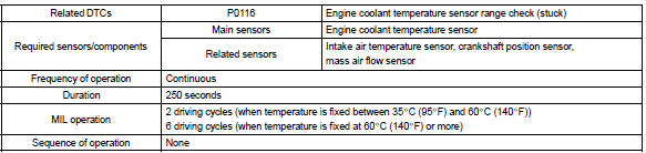
| P0116 | If engine coolant temperature (ect) was between 35 c (95 °F)
and 60 c (140 °F) when starting the engine, and also conditions
(a) and (b) are met:
|
|
If engine coolant temperature (ect) was more than 60 c
when starting the engine, and also conditions (a) and (b) are
met:
|
Monitor description
The engine coolant temperature (ect) sensor is used to monitor the engine coolant temperature. The ect sensor has a thermistor that varies its resistance depending on the temperature of the engine coolant. When the coolant temperature is low, the resistance in the thermistor increases. When the temperature is high, the resistance drops. The variations in resistance are reflected in the voltage output from the sensor. The ecm monitors the sensor voltage and uses this value to calculate the engine coolant temperature. When the sensor output voltage deviates from the normal operating range, the ecm interprets this as a fault in the ect sensor and sets a dtc.
Examples:
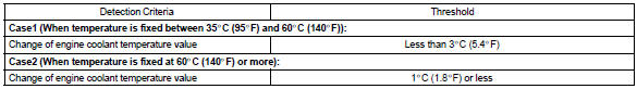
- upon starting the engine, the coolant temperature (ect) was
between 35 c (95 °F) and 60 c (140 °F).
If after driving for 250 seconds, the ect still remains within 3 c (5.4 °F) of the staring temperature, a dtc will be set. (2 Trip detection logic)
- upon starting the engine, the coolant temperature (ect) was over 60 c (140 °F). If after driving for 250 seconds, the ect still remains within 1 c (1.8 °F) of the starting temperature, a dtc will be set. (6 Trip detection logic)
Monitor strategy
Typical enabling conditions
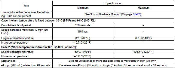
Typical malfunction thresholds
Component operating range

Wiring diagram
Refer to dtc p0115


Other materials:
Out side moulding
Replacement
Hint:
use the same procedures for the rh side and lh side.
1. Remove outside moulding
Put protective tape around the moulding.
insert a piano wire between the vehicle body and moulding.
tie objects that can serve as handles (for example, wooden
blocks) to all ...
Precaution
Caution:
the corolla is equipped with srs, which comprises a driver airbag,
front passenger airbag
and side airbag. Failure to carry out service operations in the correct
sequence could cause
the srs to unexpectedly deploy during servicing, possibly leading to a
serious accident. Fu ...
Circuit description
When the idle switch is turned on, a signal is sent to the cruise control ecu
assy. The cruise control ecu
assy uses this signal to correct the discrepancy between the throttle valve
position and the actuator position
sensor values to enable accurate cruise control at the set speed. If the idl ...