Toyota Corolla (E120) 2002–2008 Repair Manual / Diagnostics / Sfi system / Camshaft position ”a” –timing over / Circuit description
Toyota Corolla (E120): Circuit description
Refer to dtc p0010
|
Dtc no. |
Dtc detection condition |
Trouble area |
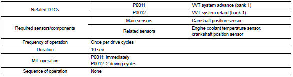
| P0011 | Condition (a) or (b) continues after engine is warmed up and
engine speed at 550 to 4,000 rpm (problem of the advanced
ocv):
|
|
| P0012 | Condition (a) or (b) continues after engine is warmed up and
engine speed at 550 to 4,000 rpm (problem of the retarded
ocv):
|
Monitor description
The ecm optimizes the valve timing using the variable valve timing (vvt) system to control the intake valve camshaft. The vvt system includes the ecm, the oil control valve (ocv) and the vvt controller. The ecm sends a target ”duty–cycle” control signal to the ocv. This control signal, applied to the ocv, regulates the oil pressure supplied to the vvt controller. The vvt controller can advance or retard the intake valve camshaft.
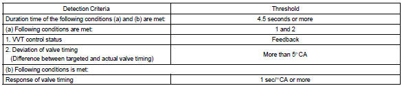
Example: when a difference between the targeted and actual valve timing is more than 5 camshaft angle ”ca” and this condition continues for more than 4.5 Sec, and if the ocv is forcibly activated 63 times or more.
Advanced cam dtcs are subject to ”1 trip” detection logic.
Retarded cam dtcs are subject to ”2 trip” detection logic.
Monitor strategy
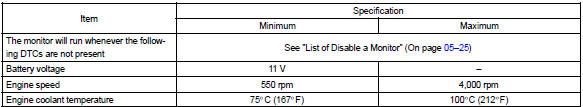
Typical enabling conditions
Typical malfunction thresholds
Wiring diagram
Refer to dtc p0010


Other materials:
Inspection procedure
1 Check fuse(ecu–ig)
Remove the ecu–ig fuse from the instrument panel j/b.
check the continuity of the ecu–ig fuse.
Ok: continuity
2 Inspect terminal voltage(b)
Remove the cruise control ecu assy with connector still
connected.
turn the ignition switch ...
System description
The ecm uses signals from the vehicle speed sensor and crankshaft position
sensor to detect the actual
gear position (1st, 2nd, 3rd or o/d gear).
Then the ecm compares the actual gear with the shift schedule in the ecm memory
to detect the mechanical
trouble of the shift solenoid valves, th ...
If your vehicle overheats
The following may indicate that your vehicle is overheating.
● Vehicles without a multi-information display: The high engine coolant temperature
warning light comes on or a loss of power is experienced.
Vehicles with a multi-information display: The engine coolant temperature gauge&n ...