Toyota Corolla (E120): Check open circuit
- For the open circuit in the wire harness in fig. 1, Perform a resistance check in step (b) or a voltage check in step (c) to locate the section.
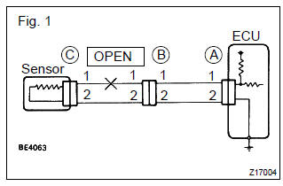
- Check the resistance.
- Disconnect connectors a and c and measure the
resistance between them.
Resistance: 1 Ω or less
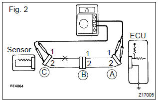
Hint
: measure the resistance while lightly shaking the wire harness vertically and horizontally. In the case of fig. 2: Between terminal 1 of connector a and terminal 1 of connector c " 10 kΩ
or higher between terminal 2 of connector a and terminal 2 of connector c " below 1 Ω
therefore, the cause is an open circuit between terminal 1 of connector a and terminal 1 of connector c.
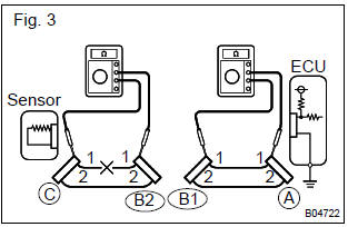
- Disconnect connector b and measure the resistance
between the connectors.
In the case of fig. 3: Between terminal 1 of connector a and terminal 1 of connector b1 " below 1 w between terminal 1 of connector b2 and terminal 1 of connector c " 10 kw therefore, the cause is an open circuit between terminal 1 of connector b2 and terminal 1 of connector c.
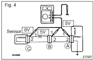
- Check the voltage.
- In a circuit in which voltage is applied (to the ecu
connector terminal), an open circuit can be checked
by conducting a voltage check.
As shown in fig. 4, With each connector still connected, measure the voltage between the body ground and terminal 1 of connector a at the ecu 5 v output terminal, terminal 1 of connector b, and terminal 1 of connector c, in that order.
- If the results are: 5 v: between terminal 1 of connector a and body ground 5 v: between terminal 1 of connector b and body ground 0 v: between terminal 1 of connector c and body ground therefore, the cause is an open circuit in the wire harness between terminal 1 of connector b and terminal 1 of connector c.


Other materials:
Antenna cord sub–assy
Replacement
Hint: components:
1. Remove instrument panel sub–assy upper
Hint:
refer to the procedure until the step, ”remove instrument panel sub–assy
upper” of
instrument panel sub–assy lower.
Remove the related parts as long as the antenna cord sub–assy can be
removed ...
Circuit description
The vapor pressure sensor, vsv for canister closed valve (ccv), vsv for
pressure switching valve are used
to detect abnormalities in the evaporative emission control system.
The ecm decides whether there is an abnormality in the evaporative emission
control system based on the
vapor pressur ...
Fuel system
Precaution
1. Before working on fuel system, disconnect negative (–) terminal cable
from
battery
2. Do not smoke or work near an open flame when working on fuel system
3. Keep gasoline away from rubber or leather parts
4. Work for prevent gasoline from spilling out
Remove the rear s ...