
Toyota Corolla (E170) 2014–2019 Owners Manual / Interior features / Bluetooth® phone (Multimedia system) / Bluetooth® phone message function
Toyota Corolla (E170): Bluetooth® phone message function
Received messages can be forwarded from the connected Bluetooth® phone, enabling checking and replying using the multimedia system.
Depending on the type of Bluetooth® phone connected, received messages may not be transferred to the message inbox.
If the phone does not support the message function, this function cannot be used.
Displaying “Message Inbox” screen
1 Press the “SETUP” button.
2 Select “Phone”.
3 Select  .
.
Receiving a message
When an e-mail/SMS/MMS is received, the incoming message screen pops up with sound and is ready to be operated on the screen.
1 Select to check the message.
2 Select to refuse the message.
3 Select to call the message sender.
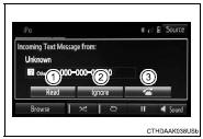
■Receiving a message
●Depending on the cellular phone used for receiving messages, or its registration status with the navigation system, some information may not be displayed.
●The pop up screen is separately available for incoming e-mail and SMS/ MMS messages under the following conditions:
E-mail:
• “Incoming E-mail Display” is set to “Full Screen”.
• “E-mail Notification Popup” is set to on.
SMS/MMS:
• “Incoming SMS/MMS Display” is set to “Full screen”.
• “SMS/MMS Notification Popup” is set to on.


Other materials:
Adjustment
Hint:
in the rh side, work in the same procedure as in the lh side.
Since the centering bolt is used as a door side hinge bolt,
the door hinge cannot be adjusted with it on. Substitute
the bolt with washer for the centering bolt.
1. Inspect rear door panel sub–assy lh
Check ...
How to proceed with troubleshooting
Hint:
troubleshooting of the wireless door lock control system is based on
the premise that the power door
lock system is operating normally. Therefore, before troubleshooting the
wireless door lock control system,
first make certain that the the power door lock system is operating
...
If you think something is wrong
If you notice any of the following symptoms, your vehicle probably needs adjustment
or repair. Contact your Toyota dealer as soon as possible.
Visible symptoms
● Fluid leaks under the vehicle.
(Water dripping from the air conditioning after use is normal.)
● Flat-looking tires or u ...