Toyota Corolla (E120): Adjustment
1. Inspect and adjust clutch pedal sub–assy
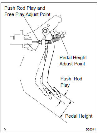
- Turn over the floor carpet.
- check that the pedal height is correct.
Pedal height from asphalt sheet: 135.8 – 145.8 Mm (5.346 – 5.740 In.)
- adjust the pedal height.
- Loosen the lock nut and turn the stopper bolt until
the height is correct. Tighten the lock nut.
Torque: 24.5 Nvm (245 Kgf·cm, 18 ft·lbf)
- check that the pedal free play and push rod play are correct.
- Depress the pedal until the clutch resistance begin
to be felt.
Pedal free play: 5.0 – 15.0 Mm (0.197 – 0591 In.)
- Gently depress the pedal until the resistance begins
to increase a little.
Push rod play at pedal top: 1.0 – 5.0 Mm (0.039 – 0.197 In.)
- Adjust the pedal free play and push rod play.
- Loosen the lock nut and turn the push rod until the free play and push rod play are correct.
- Tighten the lock nut.
- After adjusting the pedal free play, check the pedal height.
- Connect the air duct and install the lower finish panel.
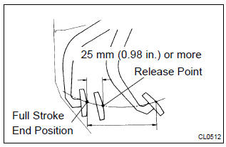
- Check the clutch release point.
- Pull the parking brake lever and install wheel stopper.
- Start the engine and idle the engine.
- Without depressing the clutch pedal, slowly shift the shift lever into reverse position until the gears contact.
- Gradually depress the clutch pedal and measure the stroke distance from the point that the gear noise stops (release point) up to the full stroke end position.
Standard distance: 25 mm (0.98 In.) Or more (from pedal stroke end position to release point) if the distance is not as specified, perform the following operations.
- Check pedal height.
- Check push rod play and pedal free play.
- Bleed the clutch line.
- Check the clutch cover assy and disc assy.


Other materials:
Child restraint system
fixed with a seat belt
A child restraint system for a
small child or baby must itself be
properly restrained on the seat
with the lap portion of the
lap/shoulder belt.
■ Installing child restraint
system using a seat belt
(child restraint lock function
belt)
Install the child restraint system
in accordance to the operat ...
Diagnostic trouble code chart
Terms
Terms
Physical address
Three–digit code (shown in hexadecimal) which is given to each
component comprising
the avc–lan.
Corresponding to the function, individual symbols are specified.
Logical address
Two–digit code (shown in hexadeci ...
Do-it-yourself service precautions
If you perform maintenance by yourself, be sure to follow the correct procedure
as given in these sections.
CAUTION
The engine compartment contains many mechanisms and fluids that may move suddenly,
become hot, or become electrically energized. To avoid death or serious injury,
observe t ...