Toyota Corolla (E120) 2002–2008 Repair Manual / Diagnostics / Sfi system / Engine coolant temperature circuit / Inspection procedure
Toyota Corolla (E120): Inspection procedure
Hint
:
- if different dtcs related to different systems that have terminal e2 as the ground terminal are output simultaneously, terminal e2 may be open.
- Read freeze frame data using the hand-held tester or the obd ii scan tool. Freeze frame data records the engine conditions when a malfunction is detected. When troubleshooting, it is useful for determining whether the vehicle was running or stopped, the engine was warmed up or not, the air–fuel ratio was lean or rich, etc. At the time of the malfunction.
1 Read value of hand–held tester or obd ii scan tool(engine coolant temperature)
- Connect the hand–held tester or the obd ii scan tool to the dlc3.
- turn the ignition switch on and push the hand–held tester or the obd ii scan tool main switch on.
- select the item ”diagnosis / enhanced obd ii / data list / all / coolant temp” and read its value displayed on the hand–held tester or the obd ii scan tool.
Temperature: same value as the actual intake air temperature.
Result:

Hint
: if there is an open circuit, the hand–held tester or the obd ii scan tool indicates –40 °C (–40°f).
If there is a short circuit, the hand–held tester or the obd ii scan tool indicates 140 °C (284°f) or more.


2 Read value of hand–held tester or obd ii scan tool(check for open in wire harness)
- Disconnect the e2 engine coolant temperature sensor connector.
- connect terminals 1 and 2 of the engine coolant temperature sensor connector on the wire harness side.
- turn the ignition switch on.
- select the item ”diagnosis / enhanced obd ii /
data list / all / coolant temp” and read its value
displayed on the hand–held tester or the obd ii scan tool.
Temperature value: 140 °C (284°f) or more
- reconnect the engine coolant temperature sensor connector.


3 Read value of hand–held tester or obd ii scan tool(check for open in ecm)

- Disconnect the e2 engine coolant temperature sensor connector.
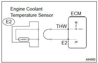
- connect the terminals thw and e2 of the e3 ecm connector.
Hint
: before checking, do a visual and contact pressure check on the ecm connector.
- turn the ignition switch on.
- select the item ”diagnosis / enhanced obd ii /
data list / all / coolant temp” and read its value
displayed on the hand–held tester or the obd ii scan tool.
Temperature value: 140 °C (284°f) or more
- reconnect the engine coolant temperature sensor connector.


Confirm good connection at ecm. If ok, replace ecm
4 Read value of hand–held tester or obd ii scan tool(check for short in wire harness)

- Disconnect the e2 engine coolant temperature sensor connector.
- turn the ignition switch on.
- select the item ”diagnosis / enhanced obd ii /
data list / all / coolant temp” and read its value
displayed on the hand–held tester or the obd ii scan tool.
Temperature value: –40 °C (–40°f)
- reconnect the engine coolant temperature sensor connector.


5 Read value of hand–held tester or obd ii scan tool(check for short in ecm)

- Disconnect the e3 ecm connector.
- turn the ignition switch on.
- ) select the item ”diagnosis / enhanced obd ii /
data list / all / coolant temp” and read its value
displayed on the hand–held tester or the obd ii scan tool.
Temperature: –40 °C (–40°f)
- reconnect the ecm connector.


Replace ecm


Other materials:
Emission inspection and maintenance (I/M) programs
Some states have vehicle emission inspection programs which include OBD (On
Board Diagnostics) checks. The OBD system monitors the operation of the emission
control system.
If the malfunction indicator lamp comes on
The OBD system determines that a problem exists somewhere in the emission cont ...
Inspection procedure
Hint:
read freeze frame data using the hand–held tester or the obd ii scan tool.
Freeze frame data records the
engine conditions when a malfunction is detected. When troubleshooting, it is
useful for determining whether
the vehicle was running or stopped, the engine was warmed up or not, th ...
Inspection procedure
1 Inspect ecm(+b voltage)
Turn the ignition switch on.
measure the voltage between the terminals of the e4 and
e6 ecm connectors.
Standard:
2 Check harness and connector(ecm – body ground)
Disconnect the e4 ecm connector.
check the resistance between the wire ...