Toyota Corolla (E120) 2002–2008 Repair Manual / Diagnostics / Sfi system / Engine coolant temperature circuit / Circuit description
Toyota Corolla (E120): Circuit description
A thermistor is built in the engine coolant temperature sensor and changes the resistance value according to the engine coolant temperature.
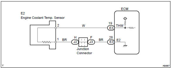
The structure of the sensor and connection to the ecm is the same as those of the intake air temperature sensor.
Hint
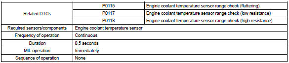
: if the ecm detects the dtc p0115, p0117 or p0118, it operates the fail–safe function in which the engine coolant temperature is assumed to be 80 c (176 °F).
|
Dtc no. |
Proceed to |
Dtc detection condition |
Trouble area |
| P0115 | Step 1 | Open or short in engine coolant temperature sensor circuit for 0.5 Seconds |
|
| P0117 | Step 4 | Short in engine coolant temperature sensor circuit for 0.5 Seconds | |
| P0118 | Step 2 | Open in engine coolant temperature sensor circuit for 0.5 Seconds |
Hint
: after confirming dtc p0115, p0117 or p0118, confirm the engine coolant temperature in the ”diagnosis/ enhanced obd ii/data list/all” using the hand–held tester or the obd ii scan tool.
Monitor description
The engine coolant temperature (ect) sensor is used to monitor the engine coolant temperature. The ect sensor has a thermistor that varies its resistance depending on the temperature of the engine coolant. When the coolant temperature is low, the resistance in the thermistor increases. When the temperature is high, the resistance drops. The variations in resistance are reflected in the voltage output from the sensor. The ecm monitors the sensor voltage and uses this value to calculate the engine coolant temperature. When the sensor output voltage deviates from the normal operating range, the ecm interprets this as a fault in the ect sensor and sets a dtc.
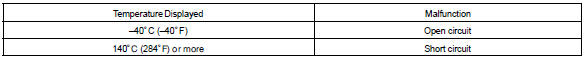
Example: when the ecm calculates that the ect is –40 c (–40 °F), or more than 140 c (284 °F), and if either the condition continues for 0.5 Sec or more, the ecm will set a dtc.
Monitor strategy
Typical enabling conditions

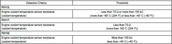
Typical malfunction thresholds
Component operating range

Wiring diagram


Other materials:
Circuit description
The srs warning light is located on the combination meter.
When the srs is normal, the srs warning light lights up for approx. 6 Seconds
after the ignition switch is
turned from the lock position to on position, and then turns off automatically.
If there is a malfunction in the srs, the srs ...
Overhaul
Hint: components:
1. Remove rear wheel
2. Remove spare wheel cover assy
3. Remove rear floor finish plate
4. Remove luggage compartment trim cover inner lh
5. Remove rear shock absorber with coil spring
Support the rear axle beam with jack.
Remove the 2 nuts and bolt.
...
Inspection procedure
1 Inspect parking brake switch circuit
Check for open and short circuit in parking brake switch circuit
2 Inspect brake fluid level warning switch circuit
Check the brake fluid level in reservoir.
check for open and shot circuit in brake fluid level warning
switch circuit
...