Toyota Corolla (E120) 2002–2008 Repair Manual / Diagnostics / Sfi system / Engine coolant temp. Circuit
range/performance problem / Circuit description
Toyota Corolla (E120): Circuit description
Refer to dtc p0115
|
Dtc no. |
Dtc detection condition | Trouble area |
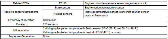
| P0116 | If engine coolant temperature (ect) was between 35 c (95 °F)
and 60 c (140 °F) when starting the engine, and also conditions
(a) and (b) are met:
|
|
If engine coolant temperature (ect) was more than 60 c
when starting the engine, and also conditions (a) and (b) are
met:
|
Monitor description
The engine coolant temperature (ect) sensor is used to monitor the engine coolant temperature. The ect sensor has a thermistor that varies its resistance depending on the temperature of the engine coolant. When the coolant temperature is low, the resistance in the thermistor increases. When the temperature is high, the resistance drops. The variations in resistance are reflected in the voltage output from the sensor. The ecm monitors the sensor voltage and uses this value to calculate the engine coolant temperature. When the sensor output voltage deviates from the normal operating range, the ecm interprets this as a fault in the ect sensor and sets a dtc.
Examples:
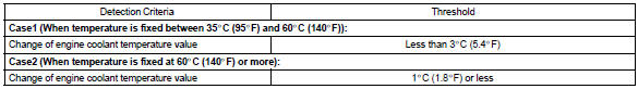
- upon starting the engine, the coolant temperature (ect) was
between 35 c (95 °F) and 60 c (140 °F).
If after driving for 250 seconds, the ect still remains within 3 c (5.4 °F) of the staring temperature, a dtc will be set. (2 Trip detection logic)
- upon starting the engine, the coolant temperature (ect) was over 60 c (140 °F). If after driving for 250 seconds, the ect still remains within 1 c (1.8 °F) of the starting temperature, a dtc will be set. (6 Trip detection logic)
Monitor strategy
Typical enabling conditions
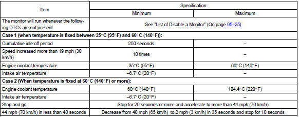
Typical malfunction thresholds
Component operating range

Wiring diagram
Refer to dtc p0115


Other materials:
Inspection procedure
Hint:
this dtc chart is on the premise that the engine is cranked normally.
If the engine is not cranked, proceed
to the problem symptoms table on page 05–42.
Read freeze frame data using the hand-held tester or the obd ii scan
tool. Freeze frame data records
the engine conditions ...
Circuit description
The shift solenoid valve sl is turned ”on” and ”off” by signals from the ecm
in order to control the hydraulic
pressure operation, the lock–up relay valve, which then the controls operation
of the lock–up clutch.
Fail safe function:
if the ecm detects a malfunction, it turns the ...
Phone screen
To display the screen shown below, press the
switch on the steering wheel or the
button.
Several functions are available to operate on each screen that is displayed by
selecting the 4 tabs.
1 Device name
2 Bluetooth® connection status
■ Telephone switch
■ Microphone
υ ...