Toyota Corolla (E120) 2002–2008 Repair Manual / Emission control / Valve clearance
Toyota Corolla (E120): Valve clearance
Adjustment
1. Remove cylinder head cover no.2
- Remove the 2 nuts, 2 clips and cylinder head cover.
2. Disconnect engine wire
- Remove the 5 clamps from the 5 clamp brackets.
- Disconnect the 4 ignition coil connectors.
- Remove the bolt and nut installing the engine wire.
3. Remove ignition coil assy
- Remove the 4 bolts and 4 ignition coils.
4. Disconnect ventilation hose
- Disconnect the ventilation hose from the cylinder head cover.
5. Disconnect ventilation hose no.2
- Disconnect the ventilation hose from the cylinder head cover.
6. Remove cylinder head cover sub–assy
- Remove the 9 bolts, 2 seal washers, 2 nuts, 3 clamp brackets and cylinder head cover.
7. Remove engine under cover rh
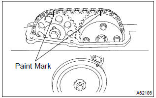
8. Set no. 1 Cylinder to tdc/compression
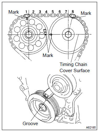
- Turn the crankshaft pulley, and align its groove with timing mark ”0” of the timing chain cover.
- check that the point marks of the camshaft timing sprocket and vvt timing sprocket are in straight line on the timing chain cover surface as shown in the illustration.
Hint
: if not, turn the crankshaft 1 revolution (360 ) and align the marks as above.
9. Inspect valve clearance
- Check only the valves indicated.
- Using a feeler gauge, measure the clearance between the valve lifter and camshaft.
- Record the out–of specification valve clearance
measurements. They will be used later to determine
the required replacement valve lifter.
Valve clearance (cold): intake 0.15 – 0.25 Mm (0.0059 – 0.0098 In.) Exhaust 0.25 – 0.35 Mm (0.0098 – 0.0138 In.)
- turn the crankshaft 1 revolution (360 ) and set no. 4 Cylinder to tdc/compression.
- Check only the valves indicated.
- Using a feeler gauge, measure the clearance between the valve lifter and camshaft.
- Record the out–of specification valve clearance
measurements. They will be used later to determine
the required replacement valve lifter.
Valve clearance (cold): intake 0.15 – 0.25 Mm (0.0059 – 0.0098 In.) Exhaust 0.25 – 0.35 Mm (0.0098 – 0.0138 In.)
10. Remove fan and generator v belt
- Turn the v–ribbed belt tensioner slowly clockwise and loosen it. Then, remove the fan and generator v belt and put back the v–ribbed belt tensioner little by little and fix it quietly.
11. Remove engine mounting insulator sub–assy rh
- Remove the ps oil pump reservoir and put it aside.
- place a wooden block between the jack and engine, and set the jack, then remove the 4 bolts, the 2 nuts and engine mounting insulator rh.

12. Remove v–ribbed belt tensioner assy
- Remove the bolt, nut and v–ribbed belt tensioner.
Hint
: handle a jack up and down to remove the bolt.
13. Adjust valve clearance
Notice
: be sure not to revolve the crankshaft without the chain tensioner.
- Set the no. 1 Cylinder to the tdc/compression.
- place match marks on the timing chain and camshaft timing sprockets.
- Remove the 2 nuts and chain tensioner.
- Fix the camshaft with a spanner and so on, then loosen the camshaft timing gear set bolt.
Notice
: be careful not to damage the valve lifter.
- Loosen the camshaft bearing cap bolts on no. 2 Camshaft in the order as shown in the illustration in several passes,and remove the caps.
- Remove the camshaft timing gear as shown in the illustration.
- Loosen the camshaft bearing cap bolts on camshaft in the order as shown in the illustration in several passes,and remove the caps.
- Remove the camshaft with holding the timing chain.
- Tie the timing chain with a string as shown in the illustration.
Notice
: be careful not to drop anything inside the timing chain cover.
- Remove the valve lifters.
- using a micrometer, measure the thickness of the removed lifter.
- calculate the thickness of a new lifter so that the valve clearance comes within the specified value.
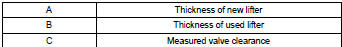
Valve clearance:
intake a = b + (c – 0.20 Mm (0.0079 In.)
Exhaust a = b + (c – 0.30 Mm (0.0118 In.)
Hint
:
- select a new lifter with a thickness as close as possible to the calculated values.
- Lifter are available in 35 sizes in increments of 0.020 Mm (0.0008 In.), From 5.060 Mm (0.1992 In.) To 5.740 Mm (0.2260 In.).
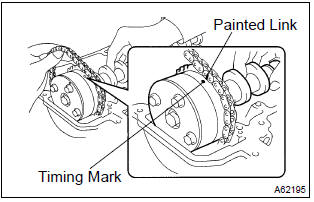
- As shown in the illustration, install the timing chain on the camshaft timing gear, with the painted links aligned with the timing marks on the camshaft timing sprocket.
- Examine the front marks and numbers and tighten the
bolts in the order shown in the illustration.
Torque: 13 nvm (133 Kgf·cm, 10 ft·lbf)
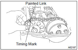
- Put the camshaft no.2 On the cylinder head with the painted links of the chain aligned with the timing mark on the camshaft timing sprocket.
- Tighten the camshaft timing gear set bolt temporarily.
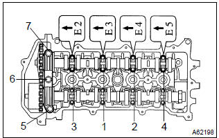
- Examine the front marks and numbers and tighten the
bolts in the order shown in the illustration.
Torque: 13 nvm (133 Kgf·cm, 10 ft·lbf)
- install the bearing cap no. 1.
Torque: 23 nvm (235 Kgf·cm, 17 ft·lbf)
- Fix the camshaft with a spanner and so on, then tighten
the camshaft timing gear set bolt.
Torque: 54 nvm (551 Kgf·cm, 40 ft·lbf)
Notice
: be careful not damage the valve lifter.
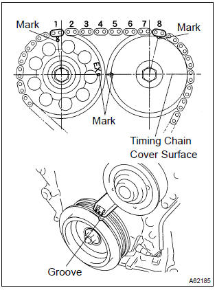
- Check the match marks on the timing chain and camshaft timing sprockets, and then the alignment of the pulley groove with timing mark of the chain cover as shown in the illustration.
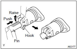
- Install chain tensioner.
- Check the o–ring is clean, and set the hook as shown in the illustration.
- Apply engine oil to the chain tensioner and install it
with the 2 nuts.
Torque: 9.0 Nvm (92 Kgf·cm, 80 invlbf)
Notice
: when installing the tensioner, set the hook again if the hook release the plunger.
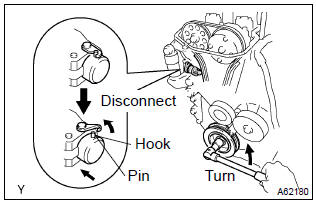
- Turn the crankshaft counterclockwise, and disconnect the plunger knock pin from the hook.
- Turn the crankshaft clockwise, and check that the slipper is pushed by the plunger.
Hint
: if the plunger does not spring out, press the slipper into the chain tensioner with a screwdriver so that the hook is released from the knock pin and the plunger springs out.
14. Install v–ribbed belt tensioner assy
- Install the v–ribbed belt tensioner with the nut and bolt.
Torque:
29 nvm (296 Kgf·cm, 21 ft·lbf) for nut 69 nvm (704 Kgf·cm, 51 ft·lbf) for bolt
15. Install engine mounting insulator sub–assy rh
- Install engine mounting insulator rh with the 4 bolts and
the 2 nuts.
Torque: 52 nvm (530 Kgf·cm, 38 ft·lbf)
16. Install cylinder head cover sub–assy
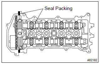
- Remove any old packing (fipg) material.
- apply seal packing to 2 locations as shown in the illustration.
Seal packing: part no. 08826–00080 Or equivalent
Notice
:
- remove any oil from the contact surface.
- Install the cylinder head cover within 3 minutes after applying seal packing.
- Do not put into engine oil 2 hours after installing.
- Install the cylinder head cover and cable bracket with the
9 bolts, 2 seal washers and 2 nuts. Uniformly tighten the
bolts and nuts, in the several passes.
Torque:
a 11 nvm (112 Kgf·cm, 8 ft·lbf) b 9.0 Nvm (92 Kgf·cm, 80 invlbf)
17. Install ignition coil assy
- Install the 4 ignition coils with the 4 bolts.
Torque: 9.0 Nvm (92 Kgf·cm, 80 in.Vlbf)
18. Install engine wire
- Install the engine wire with the bolt and nut.
Torque: 9.0 Nvm (92 Kgf·cm, 80 in.Vlbf)
19. Install cylinder head cover no.2

- Install the cylinder head cover with the 2 nuts and 2 clips.
Torque: 7.0 Nvm (71 Kgf·cm, 62 in.Vlbf)
20. Check engine oil leak


Other materials:
Replacement
Hint:
installation is according to the reverse order of the removal.
1. Remove rear door weatherstrip rh
2. Remove rear door weatherstrip lh
3. Remove rear seat cushion assy (, 72–8)
4. Remove rear seat back assy (fixed type rear seat)
5. Remove separate type rear seat back assy (separate ...
Inspection procedure
1 Check courtesy lamp switch
Check the courtesy switch, as shown in the illustration
and table.
Standard:
2 Check wire harness (integration relay door courtesy sw)
Disconnect the integration relay and door courtesy connectors.
check the continuity between th ...
Inspection procedure
1 Prepare for inspection
Disconnect the negative (–) terminal cable from the battery, and wait at
least for 90 seconds.
remove the horn button assy .
disconnect the connector of the instrument panel passenger airbag assy
.
disconnect the connector of the front sea ...