Toyota Corolla (E120): Replacement
1. Remove engine under cover rh
2. Remove cylinder head cover no.2

- Remove the 2 screw, 3 clips and engine under cover.
3. Remove fan and generator v belt
- Turn the v–ribbed belt tensioner slowly clockwise and loosen it. Then, remove the fan and generator v belt and put back the v–ribbed belt tensioner little by little and fix it quietly.
4. Remove engine mounting insulator sub–assy rh
- Remove the ps oil pump reservoir and put it aside.
- place a wooden block between the jack and engine, and set the jack, then remove the 4 bolts, the 2 nuts and engine mounting insulator rh.
5. Disconnect engine wire
- Remove the 5 clamps from the 5 clamp brackets.
- disconnect the 4 ignition coil connectors.
- Remove the bolt and nut installing the engine wire.
6. Remove ignition coil assy
- Remove the 4 bolts and 4 ignition coils.
7. Disconnect ventilation hose
- Disconnect the ventilation hose from the cylinder head cover.
8. Disconnect ventilation hose no.2
- Disconnect the ventilation hose from the cylinder head cover.
9. Remove cylinder head cover sub–assy
- Remove the 9 bolts, 2 seal washers, 2 nuts, 3 clamp brackets and cylinder head cover.
10. Set no. 1 Cylinder to tdc/compression
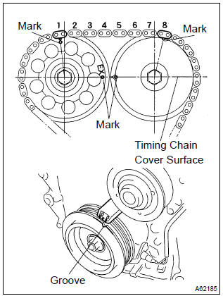
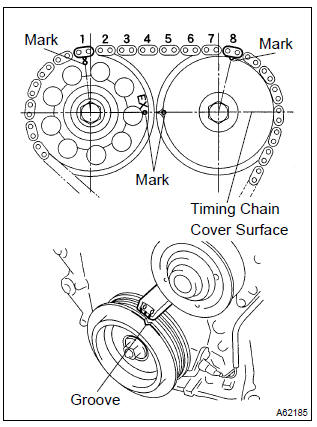
- Turn the crankshaft pulley, and align its groove with timing mark ”0” of the timing chain cover.
- check that the point marks of the camshaft timing sprocket and vvt timing sprocket are in straight line on the timing chain cover surface as shown in the illustration.
Hint
: if not, turn the crankshaft 1 revolution (360 ) and align the marks as above.
11. Remove v–ribbed belt tensioner assy
- Remove the bolt, nut and v–ribbed belt tensioner.
Hint
: handle a jack up and down to remove the bolt.
12. Remove camshaft
Notice
: be sure not to revolve the crankshaft without the chain tensioner.
- set the no. 1 Cylinder to the tdc/compression.
- place match marks on the timing chain and camshaft timing sprockets.
- Remove the 2 nuts and chain tensioner.
- Fix the camshaft with a wrench and so on, then loosen the camshaft timing gear set bolt.
Notice
: be careful not to damage the valve lifter.
- Loosen the camshaft bearing cap bolts on no. 2 Camshaft in the order as shown in the illustration in several passes,and remove the caps.
- Remove the camshaft timing gear as shown in the illustration.
- Loosen the camshaft bearing cap bolts on camshaft in the order as shown in the illustration in several passes,and remove the caps.
- Remove the camshaft with holding the timing chain.
- Tie the timing chain with a string as shown in the illustration.
Notice
: be careful not to drop anything inside the timing chain cover.
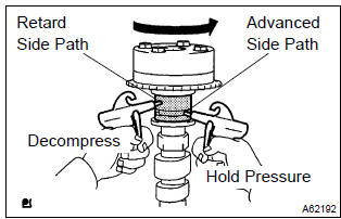
13. Inspect camshaft timing gear assy
- Check the lock of camshaft timing gear.
- Grip the camshaft with a vice, and confirm the camshaft timing gear is locked.
Notice
: be careful not to damage the camshaft.
- release lock pin.
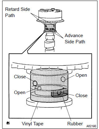
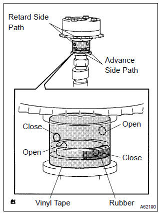
- Cover 4 oil paths of cam journal with vinyl tape as shown in the illustration.
Hint
: two advance side paths are provided in the groove of the camshaft.
Plug one of the path with a rubber piece.
- Break through the tapes of the advance side path and the retard side path on the opposite side of the groove.
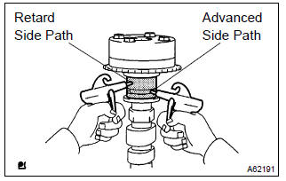
- Put air pressure into two broken paths (the advance side path and the retard side path) with about 150 kpa {1.5 Kgf·cm}.
Caution
: cover the pathes with shop rag to avoid oil splashing.
- Confirm if the camshaft timing gear assembly revolves in the timing advance direction when weakening the air pressure of the timing retard path.
Hint
: the lock pin is released, and camshaft timing gear, revolves in the advance direction.
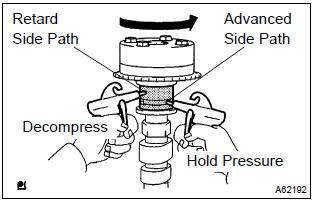
- When the camshaft timing gear comes to the most advanced position, take out the air pressure of the timing retard side path, and then, take out that of timing advance side path.
Caution
: camshaft timing assembly gear occasionally shifts to the retard side abruptly, if the air compression of the advanced side path is released before retard side path. It often causes the breakage of the lock pin.
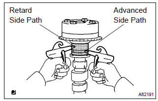
- check smooth revolution
- revolve the camshaft timing gear assembly within the movable range except for the most retarded position several times, and check the smooth revolution.
Caution
: be sure to perform this check by hand, instead of air pressure.
- check the lock in the most retarded position.
- Confirm that the camshaft timing gear assembly is locked at the most retarded position.
14. Remove camshaft timing gear assy
- Grip the camshaft with a vice, and confirm that it the gear
locked.
Caution
: be careful not to damage the camshaft.
- cover 4 oil paths of cam journal with vinyl tape as shown
in the illustration.
Hint
: two advance side paths are provided in the groove of the camshaft.
Plug one of the path with a rubber piece.
- break through the tapes of the advance side path and the retard side path on the opposite side of the groove.
- Put air pressure into two broken paths (the advance side path and the retard side path) with about 150 kpa {1.5 Kgf·cm}.
Caution
: cover the pathes with shop rag to avoid oil splashing.
- Confirm if the camshaft timing gear assembly revolves in
the timing advance direction when weakening the air
pressure of the timing retard path.
Hint
: the lock pin is released, and camshaft timing gear revolves in the advance direction.
- when the camshaft timing gear comes to the most advanced position, take out the air pressure of the timing retard side path, and then, takeout that of timing advance side path.
Caution
: camshaft timing gear assembly occasionally shifts to the retard side abruptly, if the air compression of the advanced side path is released before retard side paths. It often causes the breakage of the lock pin.
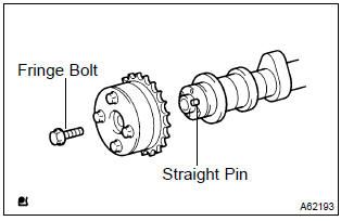
- Remove the fringe bolt of camshaft timing gear assembly.
Notice
:
- be sure not to remove the other 4 bolts.
- In case of reusing the camshaft timing gear, release the strait pin locking first, and then install the gear.
15. Install camshaft timing gear assy
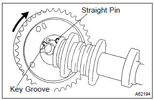
- Put the camshaft timing gear assembly and the camshaft together with the straight pin off the key groove.
- turn the camshaft timing gear assembly to the left direction
(as shown in the illustration) with pushing it lightly
against the camshaft. Push further at the position where
the pin gets into the groove.
Caution
: be sure not to turn the camshaft timing gear to the retard angle side (to the right angle).
- check that there is no clearance between the gear’s fringe and the camshaft.
- tighten the fringe bolt with the camshaft timing gear fixed.
Torque: 54 nvm (551 Kgf·cm 40 ft·lbf)
- Check that the camshaft timing gear assembly can move to the retard angle side (the right angle), and is locked at the most retarded position.
16. Install camshaft
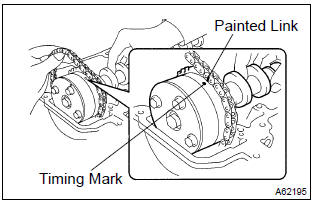
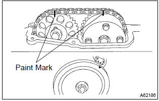
- As shown in the illustration, install the timing chain on the camshaft timing gear, with the painted links aligned with the timing marks on the camshaft timing gear.
- Examine the front marks and numbers and tighten the
bolts in the order shown in the illustration.
Torque: 13 nvm (133 Kgf·cm, 10 ft·lbf)
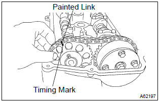
- Put the camshaft no.2 On the cylinder head with the painted links of the chain aligned with the timing mark on the camshaft timing gear.
- Tighten the camshaft timing gear set bolt temporarily.
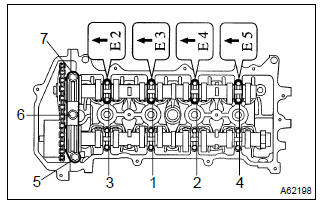
- Examine the front marks and numbers and tighten the
bolts in the order shown in the illustration.
Torque: 13 nvm (133 Kgf·cm, 10 ft·lbf)
- install the bearing cap no. 1.
Torque: 23 nvm (235 Kgf·cm, 17 ft·lbf)
- Fix the camshaft with a wrench and so on, then tighten the
camshaft timing gear set bolt.
Torque: 54 nvm (551 Kgf·cm, 40 ft·lbf)
N
otice
: be careful not damage the valve lifter.
- Check the match marks on the timing chain and camshaft timing sprockets, and then the alignment of the pulley groove with timing mark of the chain cover as shown in the illustration.
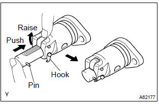
- Install chain tensioner.
- Check the o–ring is clean, and set the hook as shown in the illustration.
- Apply engine oil to the chain tensioner and install it
with the 2 nuts.
Torque: 9.0 Nvm (92 Kgf·cm, 80 invlbf)
Notice
: when installing the tensioner, set the hook again if the hook release the plunger.
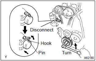
- Turn the crankshaft counter clockwise, and disconnect the plunger knock pin from the hook.
- Turn the crankshaft clockwise, and check that the slipper is pushed by the plunger.
Hint
: if the plunger does not spring out, press the slipper into the chain tensioner with a screwdriver so that the hook is released from the knock pin and the plunger springs out.
17. Adjust valve clearance
18. Install v–ribbed belt tensioner assy
- Install the v–ribbed belt tensioner with the nut and bolt.
Torque:
nut 29 nvm (296 Kgf·cm, 21 ft·lbf) bolt 69 nvm (704 Kgf·cm, 51 ft·lbf)
19. Install cylinder head cover sub–assy
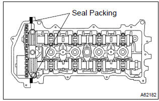
- Remove any old packing (fipg) material.
- apply seal packing to 2 locations as shown in the illustration.
Seal packing: part no. 08826–00080 Or equivalent
N
otice
:
- remove any oil from the contact surface.
- Install the cylinder head cover within 3 minutes after applying seal packing.
- Do not put into engine oil 2 hours after installing.
- Install the cylinder head cover and 3 cable brackets with
the 9 bolts, 2 seal washers and 2 nuts. Uniformly tighten
the bolts and nuts, in the several passes.
Torque:
a 11 nvm (112 Kgf·cm, 8 ft·lbf) b 9.0 Nvm (92 Kgf·cm, 80 invlbf)
20. Install ignition coil assy
- Install the 4 ignition coils with the 4 bolts.
Torque: 9.0 Nvm (92 Kgf·cm, 80 in.Vlbf)
21. Install engine wire
- Install the engine wire with the bolt and nut.
Torque: 9.0 Nvm (92 Kgf·cm, 80 in.Vlbf)
22. Install engine mounting insulator sub–assy rh
- Install engine mounting insulator with the 4 bolts and 2
nuts.
Torque: 52 nvm (530 Kgf·cm, 38 ft·lbf)
23. Install cylinder head cover no.2
- Install the cylinder head cover with the 2 nuts and 2 clips.
Torque: 7.0 Nvm (71 Kgf·cm, 62 in.Vlbf)
24. Check engine oil leak


Other materials:
Sound quality is bad in all modes (volume is too low)
Wiring diagram
Inspection procedure
1 Adjust sound quality
Adjust the sound quality.
Operate the radio receiver assy to adjust the sound quality.
Standard: malfunction disappear.
2 Compare it with another car of same model
Compare it with another vehicle of the same mo ...
Registering a Bluetooth® device
Before using the Bluetooth® audio/phone, it is necessary to register a Bluetooth®
device in the system. You can register up to 5 Bluetooth® devices.
How to register a Bluetooth® device
1 Press and select “Bluetooth*”
using .
2 Press and select “BT Pairing”
using .
A passkey w ...
Circuit description
The vapor pressure sensor, vsv for canister closed valve (ccv), vsv for
pressure switching valve are used
to detect abnormalities in the evaporative emission control system.
The ecm decides whether there is an abnormality in the evaporative emission
control system based on the
vapor pressur ...