Toyota Corolla (E120) 2002–2008 Repair Manual / Emission control / Partial engine assy / Replacement
Toyota Corolla (E120): Replacement
1. Work for preventing gasoline from spilling out
2. Remove front wheels
3. Remove engine under cover rh
4. Remove engine under cover lh
5. Drain coolant
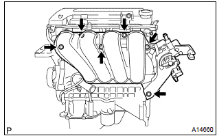
6. Remove cylinder head cover no.2
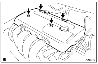
- Remove the 2 nuts, 2 clips and cylinder head cover.
7. Disconnect radiator hose inlet
- disconnect the radiator hose inlet from the radiator.
8. Disconnect radiator hose outlet
- disconnect the radiator hose outlet from the radiator.
9. Disconnect oil cooler inlet tube no.1 (A/t transaxle)
- disconnect the oil cooler inlet tube from the radiator.
10. Disconnect oil cooler outlet tube no.1 (A/t transaxle)
- disconnect the oil cooler outlet tube from the radiator.
11. Remove radiator support upper (w/ air conditioning)
- remove the 2 bolts and 2 radiator support upper.
12. Remove radiator assy (w/ air conditioning)
- disconnect the connector and harness clamp, and remove the radiator.
13. Remove battery
14. Remove battery carrier
- Remove the 4 bolts and battery carrier.
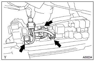
15. Remove air cleaner assembly with hose
- disconnect the mass air flow sensor connector.
- disconnect the vsv connector.
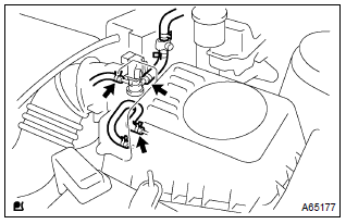
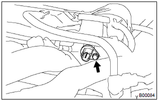
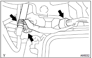
- Disconnect the 3 vacuum hoses, as shown in the illustration.
- loosen the air cleaner hose clamp and disconnect the air cleaner hose.
- remove the air cleaner cap.
- remove the air cleaner filter element.
- Disconnect the wire harness clamp, connector and hose.
- remove the 3 bolts and air cleaner case.
16. Remove efi fuel pipe clamp
17. Disconnect fuel tube sub–assy
18. Separate accelerator control cable assy
- loosen the nut, then remove the accelerator control cable.
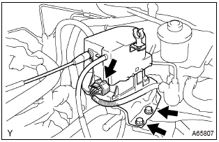
19. Separate cruise control actuator assy (w/ cruise control)
- Disconnect the actuator connector.
- remove the 2 bolts, then separate the actuator from the body.
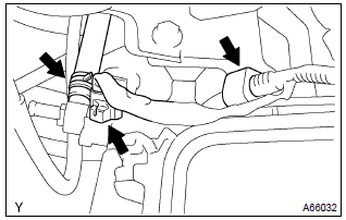
20. Disconnect union to connector tube hose
- Disconnect the union to connector tube hose from the brake booster.
21. Disconnect heater inlet water hose
- Disconnect the heater inlet water hose from the air conditioner tube.
22. Disconnect heater outlet water hose
- Disconnect the heater outlet water hose from the air conditioner tube.
23. Separate floor shift cable transmission control select (m/t transaxle)
24. Separate floor shift cable transmission control shift (m/t transaxle)
25. Separate floor shift cable transmission control shift (a/t transaxle)
26. Separate clutch release cylinder assy (m/t transaxle)
27. Remove glove compartment door assy
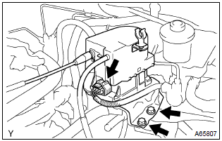
28. Disconnect engine wire
- Disconnect the engine wire from the ecm and junction block.
- pull out the engine wire.
- remove the engine room relay block cover.
- disconnect the engine wire from the engine room relay block.
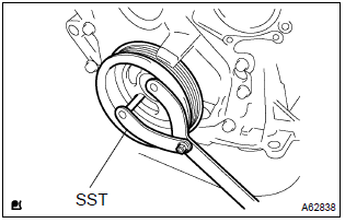
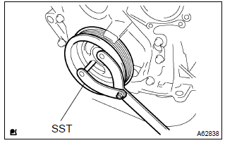
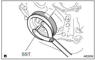
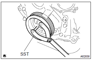
29. Remove fan and generator v belt
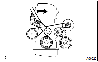
- Slowly turn the v–ribbed belt tensioner clockwise, then remove the v belt.
30. Separate compressor and magnetic clutch (w/ air conditioning)
Hint
: hang up the hoses instead of detaching.
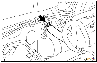
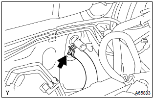
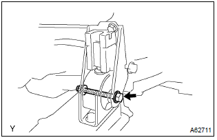
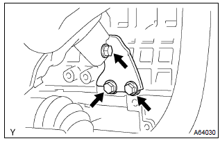
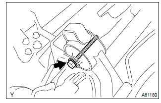
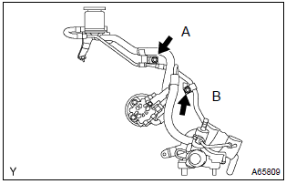
31. Separate return tube sub–assy
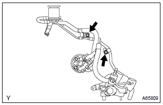
- Separate the vane pump oil reservoir from the oil reservoir bracket.
- remove the 2 bolts installing the return tube.
32. Remove front door scuff plate rh
33. Remove cowl side trim board rh
34. Remove column hole cover silencer sheet
- remove the 2 clips and column hole cover silencer sheet.
35. Separate steering intermediate shaft
36. Remove floor panel brace front
- remove the 2 nuts and floor panel brace front.
37. Remove exhaust pipe assy front
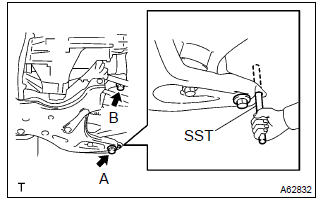
38. Remove front axle hub lh nut sst 09930–00010
39. Remove front axle hub rh nut sst 09930–00010
40. Separate tie rod end sub–assy lh sst 09628–62011
41. Separate tie rod end sub–assy rh sst 09628–62011
42. Separate front stabilizer link assy lh
43. Separate front stabilizer link assy rh
44. Separate front suspension arm sub–assy lower no.1 Lh
45. Separate front suspension arm sub–assy lower no.1 Rh
46. Separate front axle assy lh
47. Separate front axle assy rh
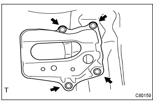
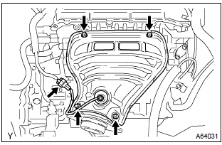
48. Remove engine assembly with transaxle
- Set the engine lifter.
- remove the 4 bolts, 2 nuts and engine mounting insulator.
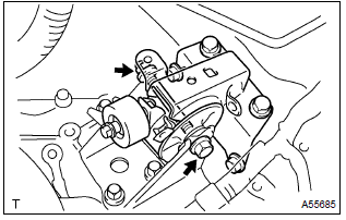
- Remove the through bolt and nut, then detach the engine mounting insulator from the vehicle.
- Remove the 6 bolts, as shown in the illustration.
- carefully, remove the engine with transaxle from the vehicle.
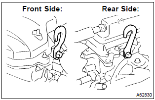
- Install the 2 engine hangers with the 2 bolts.
Part no.:
12281–15040 For no. 1 Engine hanger 12281–22021 for no. 2 Engine hanger 91512–b1016 for bolt
torque: 38 nvm (387 Kgf·cm, 28 ft·lbf)
H
int
: be sure to install the engine hanger (12281–22021) to the front side of the engine and the engine hanger (12281–15040) to the rear side.
- using the chain block and engine sling device, hang the engine assembly.
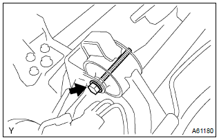
49. Separate vane pump assy
N
otice
: do not disconnect the hose.
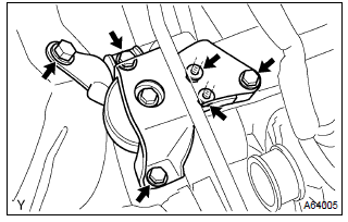
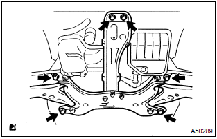
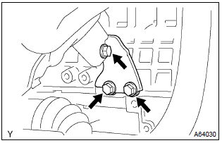
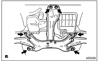
50. Remove front suspension crossmember w/center member
- Remove the through bolt and nut, then detach the engine mounting insulator fr from the engine mounting bracket.
- Remove the through bolt, then detach the engine mounting insulator rr from the suspension crossmember.
- separate the engine and transaxle assembly from the suspension crossmember and engine mounting member.
51. Remove starter assy
52. Remove manual transaxle assy (m/t transaxle)
53. Remove automatic transaxle assy (a/t transaxle)
54. Remove clutch cover assy (m/t transaxle)
55. Remove clutch disc assy (m/t transaxle)
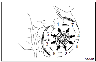
56. Remove flywheel sub–assy (m/t transaxle)
- Fix the crankshaft with sst, then remove the 8 bolts and
flywheel.
Sst 09960–10010 (09962–01000, 09963–01000)
57. Remove drive plate & ring gear sub–assy (a/t transaxle)
- Fix the crankshaft with sst, then remove the 8 bolts and
drive plate & ring gear.
Sst 09960–10010 (09962–01000, 09963–01000)
58. Remove generator assy
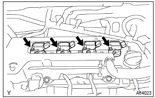
59. Remove ignition coil assy
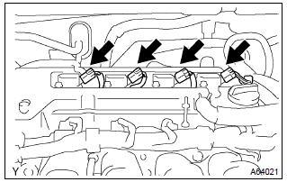
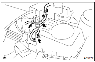
- Disconnect the 4 ignition coil connectors.
- Remove the bolt and nut installing the engine wire.
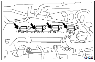
- Remove the 4 bolts and 4 ignition coils.
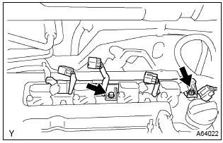
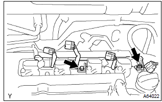
60. Remove fuel delivery pipe sub–assy
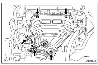
61. Remove intake manifold
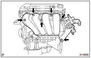
- Disconnect the 2 water hoses from the throttle body.
- disconnect the 2 vacuum hoses from the intake manifold.
- remove the 4 bolts, 2 nut, 2 wire brackets, intake manifold and throttle body assembly.
- remove the gasket from the intake manifold and throttle body assembly.
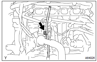
62. Remove oil level gage sub–assy
- Remove the oil level gage from the oil level gage guide.
63. Remove oil level gage guide
- Remove the bolt and oil level gage guide.
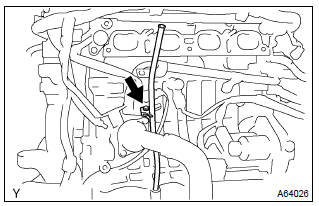
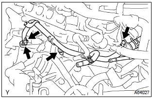
64. Remove water by–pass pipe no.1

- Remove the 2 bolts, 2 nuts, water by–pass pipe and gasket.
65. Remove water inlet
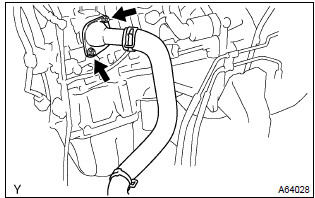
- Remove the 2 nuts and water inlet.
66. Remove thermostat
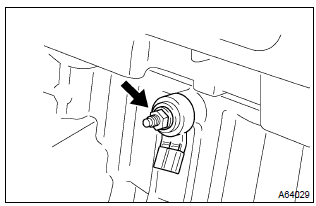
67. Remove engine oil pressure switch assy
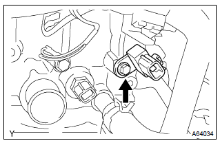
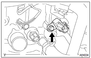
68. Remove camshaft position sensor
- Remove the bolt and camshaft position sensor.
69. Remove crankshaft position sensor
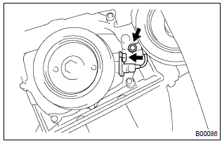
- Remove the 2 bolts and crankshaft position sensor.
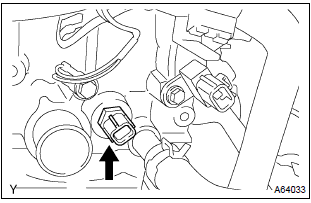
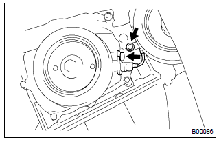
70. Remove knock sensor
- Remove the nut and knock sensor.
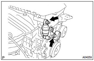
71. Remove v–ribbed belt tensioner assy
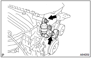
- Remove the bolts, nut and v–ribbed belt tensioner.
72. Remove manifold stay
- Remove the 3 bolts and manifold stay.
73. Remove exhaust manifold heat insulator no.1
- Remove the 4 bolts and exhaust manifold heat insulator.
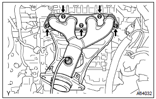
74. Remove exhaust manifold
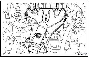
- Remove the 5 nuts, exhaust manifold and gasket.
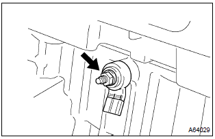
75. Remove engine coolant temperature sensor
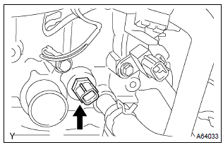
- Using sst, remove the engine coolant temperature sensor.
Sst 09817–33190
76. Remove radio setting condenser
- Remove the bolt and condenser.
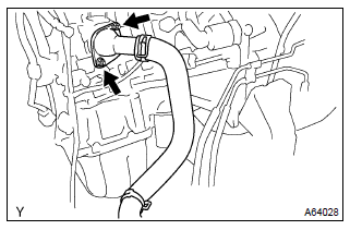
77. Remove water by–pass hose no.2
78. Remove radiator hose inlet
79. Remove heater inlet water hose
80. Replace partial engine assy
81. Install radio setting condenser
- Install the condenser with the bolt.
Torque: 10 nvm (102 Kgf·cm, 7 ft·lbf)
82. Install engine coolant temperature sensor
- Install a new gasket to the engine coolant temperature sensor.
- using sst, install the engine coolant temperature sensor.
Sst 09817–33190
torque: 20 nvm (204 Kgf·cm, 15 ft·lbf)
83. Install exhaust manifold
- Install a new gasket and the exhaust manifold with the 5
nuts.
Torque: 37 nvm (377 Kgf·cm, 27 ft·lbf)
84. Install exhaust manifold heat insulator no.1
- Install the exhaust manifold heat insulator with the 4 bolts.
Torque: 18 nvm (184 Kgf·cm, 13 ft·lbf)
85. Install manifold stay
- Install the manifold stay with the 3 bolts.
Torque: 49 nvm (500 Kgf·cm, 36 ft·lbf)
86. Install v–ribbed belt tensioner assy
- Install the v–ribbed belt tensioner with the bolt and nut.
Torque:
29 nvm (296 Kgf·cm, 21 ft·lbf) for nut 69 nvm (704 Kgf·cm, 51 ft·lbf) for bolt
87. Install knock sensor
- Install the knock sensor with the nut.
Torque: 20 nvm (204 Kgf·cm, 15 ft·lbf)
88. Install crankshaft position sensor
- Install the crankshaft position sensor with the 2 bolts.
Torque: 9.0 Nvm (92 Kgf·cm, 80 in.Vlbf)
89. Install camshaft position sensor

- Install the camshaft position sensor with the bolt.
Torque: 9.0 Nvm (92 Kgf·cm, 80 in.Vlbf)
90. Install engine oil pressure switch assy
91. Install thermostat
92. Install water inlet
- Install the water inlet with the 2 nuts.
Torque: 11 nvm (112 Kgf·cm, 8 ft·lbf)
93. Install water by–pass pipe no.1
- Install a new gasket and water by–pass with the 2 nuts
and 2 bolts.
Torque: 9.0 Nvm (92 Kgf·cm, 80 in.Vlbf)
94. Install oil level gage guide
- Apply a light coat of a new o–ring, then install it to the oil level gage guide.
- install the oil level gage guide with the bolt.
Torque: 13 nvm (133 Kgf·cm, 10 ft·lbf)
95. Install intake manifold
- Install a new gasket to the intake manifold.
- install the intake manifold and throttle body assembly with
the 2 brackets, 4 bolts and 2 nuts. Uniformly tighten the
bolts and nuts in several passes.
Torque: 30 nvm (306 Kgf·cm, 22 ft·lbf)
- connect the 2 vacuum hoses to the intake manifold.
- connect the 2 water hoses to the throttle body.
96. Install fuel delivery pipe sub–assy
97. Install ignition coil assy
- Install the 4 ignition coils with the 4 bolts.
Torque: 9.0 Nvm (92 Kgf·cm, 80 in.Vlbf)
- Install the engine wire with the bolt and nut.
Torque: 9.0 Nvm (92 Kgf·cm, 80 in.Vlbf)
98. Install generator assy
99. Install flywheel sub–assy (m/t transaxle)
- Fix the crankshaft with sst.
Sst 09960–10010 (09962–01000, 09963–01000)
- Clean the bolt and bolt hole.
- apply adhesive to the bolts.
Adhesive: part no. 09330–00070, Three bond or equivalent
- install and uniformly tighten the 8 bolts, in several passes,
in the sequence shown.
Torque: 49 nvm (500 Kgf·cm, 36 ft·lbf)
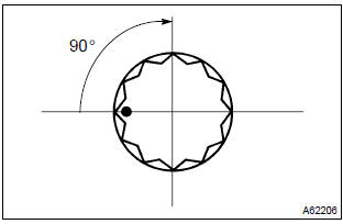
- Mark the bolts with paint.
- retighten the bolts by an additional 90 .
- check that the point marked bolts are moved by 90 angle.
100. Install drive plate & ring gear sub–assy (a/t transaxle)
- Fix the crankshaft with sst.
Sst 09960–10010 (09962–01000, 09963–01000)
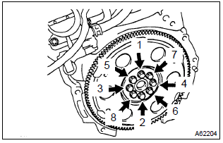
- Clean the bolt and bolt hole.
- apply adhesive to the bolts.
Adhesive: part no. 09330–00070, Three bond or equivalent
- install and uniformly tighten the 8 bolts, in several passes,
in the sequence shown.
Torque: 88 nvm (897 Kgf·cm, 65 ft·lbf)
101. Install clutch disc assy (m/t transaxle) sst 09301–00210
102. Install clutch cover assy (m/t transaxle) sst 09301–00210
103. Install manual transaxle assy (m/t transaxle)
104. Install automatic transaxle assy (a/t transaxle)
105. Install starter assy
106. Install front suspension crossmember w/center member
- Attach the engine and transaxle assembly to the suspension crossmember and engine mounting member.
- install the bolt holding the rear engine mounting bracket
to the mounting insulator.
Tmmc, nummi made:
torque: 65 nvm (663 Kgf·cm, 48 ft·lbf) takaoka, tal made:
torque: 87 nvm (887 Kgf·cm, 64 ft·lbf) - install the bolt holding the front engine mounting bracket
to the mounting insulator.
Torque: 52 nvm (530 Kgf·cm, 38 ft·lbf)
107. Install vane pump assy
108. Install engine assembly with transaxle
- Set the engine with transaxle on the engine lifter.
- install the engine with transaxle to the vehicle.
- temporarily, install the suspension crossmember and 6 bolts.
- install the engine mounting insulator lh.
Torque: 80 nvm (816 Kgf·cm, 59 ft·lbf)
- install the engine mounting insulator rh.
Torque: 52 nvm (530 Kgf·cm, 38 ft·lbf)
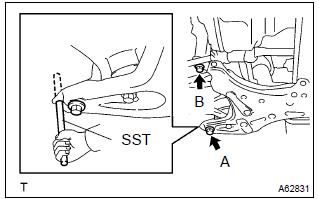
- Insert sst to the positioning holes on the right handle
crossmember and on the right–handle of the vehicle.
Sst 09670–00010
- temporarily tighten the bolt a first, then bolt b.
- Insert sst to the positioning holes on the left handle
crossmember and on the left–handle of the vehicle.
Sst 09670–00010
- ) temporarily tighten the bolt a first, then bolt b.
- insert sst to the positioning holes on the right–handle crossmember and right–handle of the vehicle, then tighten the bolts with the specified torque.
- insert sst to the positioning holes on the right–handle
crossmember and left–handle of the vehicle, then tighten
the bolts with the specified torque.
Sst 09670–00010 torque:
157 nvm (1,601 Kgf·cm, 116 ft·lbf) for bolt a 113 nvm (1,152 Kgf·cm, 83 ft·lbf) for bolt b
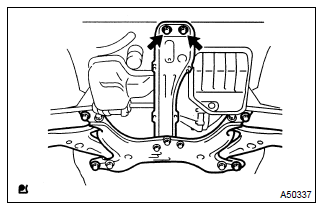
- Tighten the 2 bolts, as shown in the illustration.
Torque: 39 nvm (398 Kgf·cm, 29 ft·lbf)
N
otice
: after installing the crossmember, check that the positioning holes on the crossmember and vehicle are aligned with each other.
109. Install front suspension arm sub–assy lower no.1 Lh
110. Install front suspension arm sub–assy lower no.1 Rh
111. Install front stabilizer link assy lh
112. Install front stabilizer link assy rh
113. Install tie rod end sub–assy lh
114. Install tie rod end sub–assy rh
115. Install front axle hub lh nut
116. Install front axle hub rh nut
117. Install exhaust pipe assy front
118. Install floor panel brace front
- install the front floor panel brace with the 2 nuts.
Torque: 30 nvm (306 Kgf·cm, 22 ft·lbf)
119. Install steering intermediate shaft
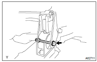
120. Install return tube sub–assy
- Install the return tube with 2 bolts.
Torque:
5.0 Nvm (51 Kgf·cm, 44 in.Vlbf) for bolt a 7.8 Nvm (80 Kgf·cm, 69 in.Vlbf) for bolt b
121. Install compressor and magnetic clutch (w/ air conditioning)
122. Install clutch release cylinder assy (m/t transaxle)
123. Install cruise control actuator assy (w/ cruise control)
- Install the actuator with the 2 bolts.
Torque: 6.0 Nvm (61 Kgf·cm, 53 in.Vlbf)
- connect the actuator connector.
124. Install air cleaner assembly with hose
- Install the air cleaner case with the 3 bolts.
Torque: 7.0 Nvm (71 Kgf·cm, 62 in.Vlbf)
- connect the wire harness clamp, connector and hose.
- install the air cleaner filter element.
- install the air cleaner cap.
- connect the air cleaner hose.
- Connect the 3 vacuum hoses, as shown in the illustration.
- connect the vsv connector.
- connect the intake air flow meter connector.
125. Install battery carrier
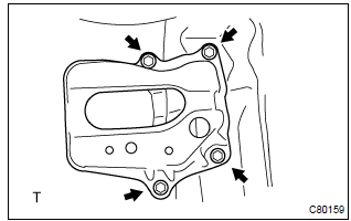
- Install the battery carrier with the 4 bolts.
Torque: 13 nvm (133 Kgf·cm, 10 ft·lbf)
126. Install battery
Torque:
5.0 Nvm (51 Kgf·cm, 44 in.Vlbf) for bolt
3.5 Nvm (36 Kgf·cm, 31 in.Vlbf) for nut
127. Install radiator support upper (w/ air conditioning)
- Install the 2 radiator support uppers with the 2 bolts.
Torque: 19 nvm (194 Kgf·cm, 14 ft·lbf)
128. Install cylinder head cover no.2
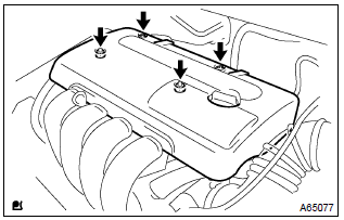
- Install the cylinder head cover with the 2 nuts and 2 clips.
Torque: 7.0 Nvm (71 Kgf·cm, 62 in.Vlbf)
129. Install front wheels torque: 103 nvm (1,050 Kgf·cm, 76 ft·lbf)
130. Add automatic transaxle fluid (a/t transaxle)
131. Add engine oil
132. Add coolant
133. Check for engine oil leaks
134. Check for engine coolant leaks
135. Check fuel leak
136. Check for exhaust gas leaks
137. Inspect check idle speed and ignition timing sst 09843–18040
138. Inspect co/hc
139. Inspect and adjust front wheel alignment
140. Check abs speed sensor signal (w/ abs)


Other materials:
Disposal
Hint:
when scrapping vehicle equipped with an srs or disposing of a horn button assy,
always first deploy the
airbag in accordance with the procedure described below. If any abnormality
occurs in the airbag deployment,
contact the service dept. Of toyota motor sales, u.S.A., Inc.
Caution:
...
Floor shift cable transmission control shift
Replacement
Hint: components:
1. Remove air conditioner unit assy
Hint:
refer to the instructions for removal of the air conditioner unit assy.
2. Separate air bag sensor assy center
remove the 3 bolts, separate the airbag sensor assy center.
3. Remove exhaust pipe assy
4. Remo ...
Child restraint system
fixed with a child restraint
LATCH anchor (except for
Puerto Rico)
■ Child restraint LATCH
anchors
LATCH anchors are provided for
the outboard rear seat. (Marks
displaying the location of the
anchors are attached to the
seats.)
■ When installing in the rear
outboard seats
Install the child restraint system
in accordance to the operation
manual enclosed with th ...