Toyota Corolla (E120): Overhaul
1. Remove cylinder block water drain cock sub–assy
- Remove the cylinder block water drain cock from the cylinder block.
2. Inspect connecting rod thrust clearance
- Using a dial indicator, measure the thrust clearance while
moving the connecting rod back and forth.
Standard thrust clearance: 0.160 To 0.342 Mm (0.0063 To 0.0135 In.) Maximum thrust clearance: 0.342 Mm (0.0135 In.)
If the thrust clearance is greater than maximum, replace the connecting rod.
If necessary, replace the crankshaft.
3. Inspect connecting rod oil clearance
Notice
: do not turn the crankshaft.
- using marking paint, write the matched cylinder number on each connecting rod and cap.
Hint
: the match marks on the connecting rods and caps are for ensuring correct reassembly.
- Using sst, remove the 2 bolts and connecting rod cap.
Sst 09205–16010
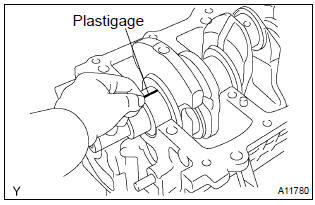
- clean the crank pin and bearing.
- check the crank pin and bearing for pitting and scratches.
- Lay a strip of the plastigage across the crank pin.
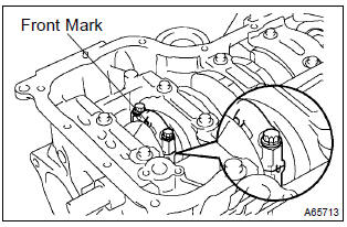
- Check that the front mark of the connecting rod cap is facing the correct direction.
- apply a light coat of engine oil on the threads and under the heads of the connecting rod cap bolts.
- Using sst, tighten the bolts in several passes by the specified
torque.
Sst 09205–16010
torque: 20 nvm (204 Kgf·cm, 15 ft·lbf)
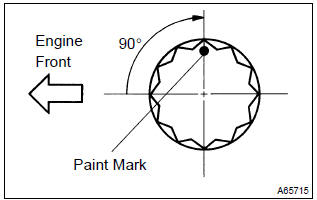
- Mark the front of the connecting cap bolts with paint.
- retighten the cap bolts by 90 as shown in the illustration.
- check that the crankshaft turns smoothly.
- Remove the 2 bolts and connecting rod cap.
- Measure the plastigage at its widest point.
Standard oil clearance: 0.028 To 0.060 Mm (0.0011 To 0.0024 In.) Maximum oil clearance: 0.080 Mm (0.0031 In.)
Notice
: remove the plastigage completely after the measurement.
- If the oil clearance is greater than maximum, replace the connecting rod bearing.
- If necessary, grind or replace the crankshaft.
Hint
: if replacing a bearing, select a new one having the same number as marked on the connecting rod. There are 3 sizes of standard bearings, marked ”1”, ”2” and ”3” accordingly.
4. Remove connecting rod sub–assy
- Using a ridge reamer, remove all the carbon from the top of the cylinder.
- Push the piston, connecting rod assembly and upper bearing through the top of the cylinder block.
Hint
: keep the bearing, connecting rod and cap together.
Arrange the piston and connecting rod assemblies in the correct order.
5. Remove connecting rod bearing
- Remove the connecting rod bearing from the connecting rod cap.
- Remove the connecting rod bearing from the connecting rod.
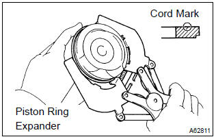
6. Remove piston ring set
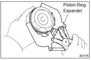
- Using a piston ring expander, remove the 2 compression rings.
- remove the 2 side rails and oil ring by hand.
7. Remove w/pin piston sub–assy
- Using a small screwdriver, pry out the 2 snap rings.
- Heat the piston to 80 to 90 c (176 to 194 f).
- Using a plastic hammer and brass bar, lightly tap out the piston pin, then remove the connecting rod.
Hint
:
- the piston and pin are a matched set.
- Arrange the piston, pin, ring, connecting rod and bearings in the correct order.
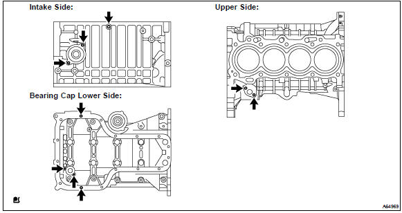
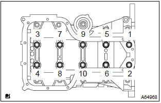
8. Remove crankshaft
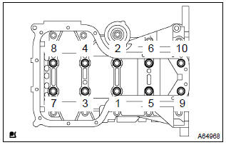
- Remove the 10 bolts.
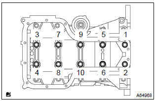
- Uniformly loosen the 10 bearing cap bolts, in several
passes, in the sequence shown in the illustration.
Sst 09011–38121
- Using a screwdriver, remove the bearing cap by prying the indicated portions between the cylinder block and bearing cap.
Notice
: be careful not to damage the contact surfaces of the cylinder block and bearing cap.
- Remove the crankshaft from the cylinder block.
9. Inspect crankshaft thrust clearance
- Using a dial indicator, measure the thrust clearance while
prying the crankshaft back and forth with a screwdriver.
Standard thrust clearance: 0.04 To 0.24 Mm (0.0016 To 0.0094 In.) Maximum thrust clearance: 0.30 Mm (0.0118 In.)
- If the thrust clearance is greater than maximum, measure the thrust washer thickness.
- If the thickness is not specified, replace the thrust washer.
Hint
: thrust washer thickness: 2.430 To 2.480 Mm (0.0957 To 0.0976 In.).
10. Remove crankshaft thrust washer upper
- Remove the 2 crankshaft thrust washers from the cylinder block.
11. Remove crankshaft bearing
- Remove the 5 crankshaft bearings from the cylinder block.
Notice
: arrange the main bearings and thrust washers in the correct order.
- Remove the 5 crankshaft bearings from the bearing cap.
Notice
: arrange the main bearings and thrust washers in the correct order.
12. Remove stud bolt
- Using torx socket wrench e5 and e7, remove the 9 stud bolts.
13. Inspect cylinder block for flatness
- Using a precision straight edge and feeler gauge, measure
the surface contacting the cylinder head gasket for
warpage.
Maximum warpage: 0.05 Mm (0.0020 In.)
If the warpage is greater than maximum, replace the cylinder block.
14. Inspect cylinder bore
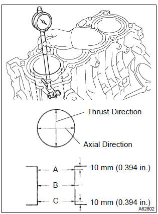
- Using a cylinder gauge, measure the cylinder bore diameter
at positions a, b and c in the thrust and axial directions.
Standard diameter:
79.000 To 79.013 Mm (3.1102 To 3.1107 In.) - calculate the difference between the maximum diameter
and minimum diameter of the 6 measured values.
Difference limit: 0.10 Mm (0.0039 In.)
If the difference is greater than limit, replace the cylinder block.
15. Inspect w/pin piston sub–assy
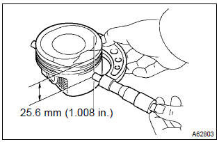
- Using a micrometer, measure the piston diameter at a
right angle to the piston pin hole, and at the piston of 25.6
Mm (1.008 In.) From the piston head.
Piston diameter:
78.872 To 78.972 Mm (3.1052 To 3.1091 In.)
16. Inspect piston oil clearance
- Subtract the piston diameter measurement from the cylinder bore diameter
measurement.
Standard oil clearance: 0.065 To 0.088 Mm (0.0026 To 0.0035 In.) Maximum oil clearance: 0.088 Mm (0.0035 In.)
- If the oil clearance is greater than maximum, replace all the pistons.
- If necessary, replace the cylinder block.
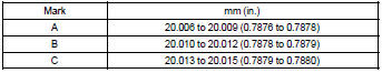
17. Inspect piston pin oil clearance
- Using a caliper gauge, measure the piston pin bore diameter.
Piston pin bore diameter: 20.006 To 20.015 Mm (0.7876 To 0.7880 In.)
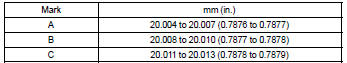
- Using a micrometer, measure the piston pin outer diameter.
Piston pin outer diameter: 20.004 To 20.013 Mm (0.7876 To 0.7879 In.)
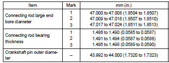
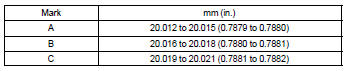
- Using a caliper gauge, measure the connecting rod small
end bore diameter.
Connecting rod small end bore diameter: 20.012 To 20.021 Mm (0.7879 To 0.7882 In.)
- Subtract the piston pin outer diameter measurement from
the piston pin bore diameter measurement.
Standard oil clearance: 0.002 To 0.011 Mm (0.0001 To 0.0004 In.) Maximum oil clearance: 0.011 Mm (0.0004 In.)
- If the oil clearance is greater than maximum, replace the connecting rod.
- If necessary, replace the w/ pin piston.
- subtract the piston pin outer diameter measurement from
the connecting rod small end bore diameter measurement.
Standard oil clearance: –0.001 To 0.017 Mm (–0.00004 To 0.0007 In.) Maximum oil clearance: 0.017 Mm (0.0007 In.)
- If the oil clearance is greater than maximum, replace the connecting rod.
- If necessary, replace the connecting rod and w/ pin piston.
18. Inspect ring groove clearance
- Using a feeler gauge, measure the clearance between
the new piston ring and the wall of the ring groove.
Ring groove clearance:
0.02 To 0.07 Mm (0.0008 To 0.0028 In.) For no. 1 Ring 0.03 To 0.07 Mm (0.0012 To 0.0028 In.) For no. 2 Ring 0.03 To 0.11 Mm (0.0012 To 0.0043 In.) For oil ring
If the groove clearance is not as specified, replace the piston ring.
19. Inspect piston ring end gap
- Using a piston, push the piston ring a little beyond the bottom of the ring travel, that means 110 mm (4.33 In.) From the top of the cylinder block.
- Using a feeler gauge, measure the end gap.
Standard end gap:
0.25 To 0.35 Mm (0.0098 To 0.0138 In.) For no. 1 Ring 0.35 To 0.50 Mm (0.0138 To 0.0197 In.) For no. 2 Ring 0.15 To 0.40 Mm (0.0059 To 0.0157 In.) For oil ring Maximum end gap:
1.05 Mm (0.0413 In.) For no. 1 Ring 1.20 Mm (0.0472 In.) For no. 2 Ring
- if the end gap is greater than maximum, replace the piston ring.
- If the end gap is greater than maximum, even with a new piston ring, replace the cylinder block.
20. Inspect connecting rod sub–assy
- Using a connecting rod aligner and feeler gauge, check the connecting rod alignment.
- Check for out–of–alignment.
Maximum out–of–alignment: 0.05 Mm (0.0020 In.) Per 100 mm (3.94 In.)
If out–of–alignment is greater than maximum, replace the connecting rod assembly.
- Check for twist.
Maximum twist:
0.05Mm (0.0020 In.) Per 100 mm (3.94 In.)
If twist is greater than maximum, replace the connecting rod assembly.
21. Inspect connecting rod bolt
- Using a vernier caliper, measure the tension portion diameter
of the bolts.
Standard diameter:
6.6 To 6.7 Mm (0.260 To 0.264 In.) Maximum diameter: 6.4 Mm (0.252 In.)
If the diameter is less than maximum, replace the connecting rod bolt.
22. Inspect crankshaft
- Using a dial indicator and v–blocks, measure the circle
runout, as shown in the illustration.
Maximum circle runout: 0.03 Mm (0.0012 In.)
If the circle runout is greater than maximum, replace the crankshaft.
- Using a micrometer, measure the diameter of each main
journal at the points shown in the illustration.
Diameter: 47.988 To 48.000 Mm (1.8893 To 1.8898 In.) If the diameter is not as specified, check the crankshaft oil clearance.
- check each main journal for taper and out–of–round as
shown.
Maximum taper and out–of–round: 0.02 Mm (0.0008 In.)
If the taper and out–of–round is greater than maximum, replace the crankshaft.
- Using a micrometer, measure the diameter of each crank
pin at the points shown in the illustration.
Diameter: 43.992 To 44.000 Mm (1.7320 To 1.7323 In.) If the diameter is not as specified, check the connecting rod oil clearance.
- check each crank pin for taper and out–of–round as
shown.
Maximum taper and out–of–round: 0.02 Mm (0.0008 In.)
If the taper and out–of–round is greater than maximum, replace the crankshaft.
23. Inspect crankshaft bearing cap set bolt
- Using a vernier caliper, measure the tension portion diameter
of the bolts.
Standard diameter: 7.3 To 7.5 Mm (0.287 To 0.295 In.) Minimum diameter: 7.3 Mm (0.287 In.)
If the diameter is greater than minimum, replace the crankshaft bearing cap set bolt.
24. Inspect crankshaft oil clearance
Notice
: do not turn the crankshaft.
- clean each main journal and bearing.
- place the crankshaft on the cylinder block.
- lay a strip of the plastigage across each journal.
- Using sst, tighten the bolts in several passes, in the sequence
shown, by the specified torque.
Sst 09011–38121
torque: 44 nvm (449 Kgf·cm, 33 ft·lbf)
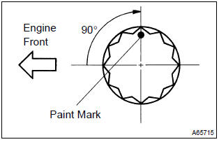
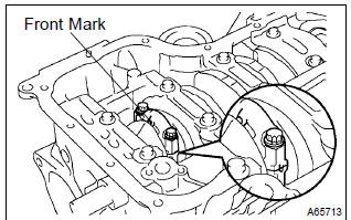
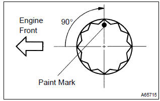
- Mark the front of the bearing cap bolts with paint.
- retighten the bearing cap bolts by 90 as shown in the illustration.
- check that the painted mark is now at a 90 angle to the front.
- Tighten the other 10 bolts for the bearing cap.
Torque: 19 nvm (194 Kgf·cm, 14 ft·lbf)
- remove the 10 bolts.
- Uniformly loosen the 10 bearing cap bolts, in several
passes, in the sequence shown in the illustration.
Sst 09011–38121
- Measure the plastigage at its widest point.
Standard oil clearance: 0.015 To 0.032 Mm (0.0006 To 0.0013 In.) Minimum oil clearance: 0.05 Mm (0.0020 In.)
Notice
: completely remove the plastigage.
- If the oil clearance is greater than minimum, replace the crankshaft bearing.
- If necessary, replace the crankshaft.
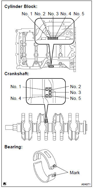
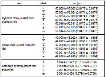
Hint
: if replacing a bearing, select a new one having the same number.
If the number of the bearing cannot be determined, calculate the correct bearing number by adding together the numbers imprinted on the cylinder block and crankshaft, then select a new bearing having the calculated number. There are 4 sizes of standard bearings, marked ”1”, ”2”, ”3” and ”4” accordingly.
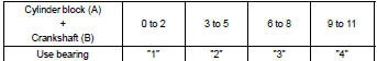
Example
: cylinder block ”3” (a) + crankshaft ”4” (b) = total number 7 (use bearing ”3”)
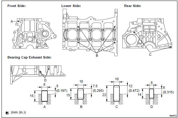
25. Install straight pin
- Using a plastic hammer, install the 9 straight pins to the
cylinder block.
Standard protrusion:
5 mm (0.197 In.) For straight pin a 7.5 Mm (0.295 In.) For straight pin b 12 mm (0.472 In.) For straight pin c 8 mm (0.315 In.) For straight pin d
26. Install ring pin
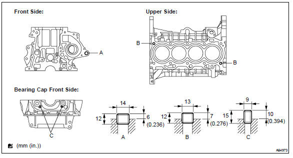
- Using a plastic hammer, install the 5 ring pins to the cylinder
block.
Standard protrusion:
6 mm (0.236 In.) For ring pin a 7 mm (0.276 In.) For ring pin b 10 mm (0.394 In.) For ring pin c
27. Install stud bolt

- Using torx socket wrench e5 and e7, install the 9 stud bolt
to the cylinder block.
Torque:
5.0 Nvm (51 Kgf·cm, 44 in.Vlbf) for stud bolt a, c, d and e
11 nvm (112 Kgf·cm, 8 ft·lbf) for stud bolt b
28. Install w/pin piston sub–assy
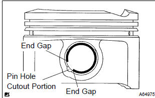
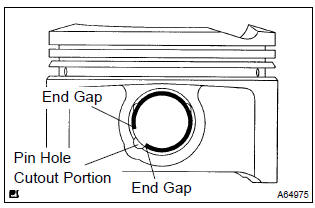
- Using a small screwdriver, install a new snap ring at one end of the piston pin hole.
Hint
: be sure that end the gap of the snap ring is aligned with the pin hole cutout portion of the piston.
- Heat the piston to 80 to 90 c (176 to 194 f).
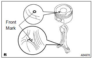
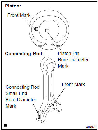
- Align the front marks on the piston with connecting rod, then push in the piston with your thumb.
- Using a small screwdriver, install a new snap ring at one end of the piston pin hole.
Hint
: be sure that the end gap of the snap ring is aligned with the pin hole cutout portion of the piston.
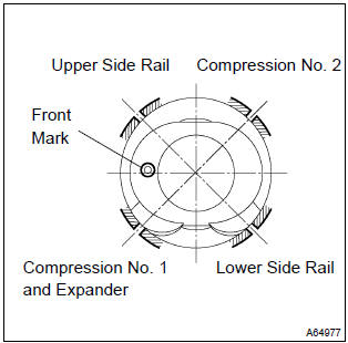
29. Install piston ring set
Hint
: in case of reusing the piston rings, install them to the matched pistons with the surfaces facing correctly.
- install the oil ring expander and 2 side rails by hand.
- using a piston ring expander, install the 2 compression
rings with the code mark facing upward.
Code mark (no. 2 Only): 2r
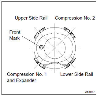
- Position the piston rings so that the ring ends are as shown.
30. Install crankshaft bearing
- Install the upper bearing with the oil groove on the cylinder block.
Notice
: do not apply engine oil to the bearing and its contact surface.
- Install the lower bearing on the bearing cap.
Notice
: do not apply engine oil to the bearing and its contact surface.
31. Install crankshaft thrust washer upper
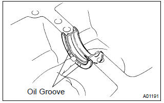
- Install the 2 thrust washers under the no. 3 Journal position of the cylinder block with the oil grooves facing outward.
32. Install crankshaft
- Apply engine oil to the upper bearing, then install the crankshaft on the cylinder block.
- apply a light coat of engine oil on the bolt threads, bolt seats, and bearings of the bearing cap.
- install the crankshaft to the cylinder block.
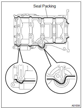
- Apply the seal packing in the shape of the bead (diameter
2.5 To 3.5 Mm (0.098 To 0.138 In.) Consequently as shown
in the illustration.
Seal packing: part no. 08826–00080 Or equivalent
Notice
:
- remove any oil from the contact surface.
- Install the bearing cap sub–assembly within 3 minutes after applying the seal packing.
- Do not put into engine oil within 2 hours of installation.
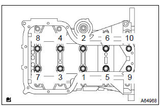
- Using sst, tighten the bolts in several passes, in the sequence
shown, by the specified torque.
Sst 09011–38121
torque: 44 nvm (449 Kgf·cm, 33 ft·lbf)
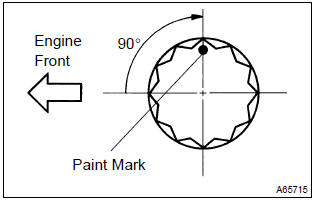
- Mark the front of the bearing cap bolts with paint.
- retighten the bearing cap bolts by 90 as shown in the illustration.
- check that the painted mark is now at a 90 angle to the front.

- Tighten the other 10 bolts for the bearing cap.
Torque: 19 nvm (194 Kgf·cm, 14 ft·lbf)
33. Install connecting rod bearing
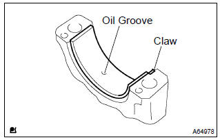
- Align the connecting rod bearing claw with the oil groove of the connecting rod cap.
- install the connecting rod bearing in the connecting rod cap.
Notice
: do not apply engine oil to the bearing and its contact surface.
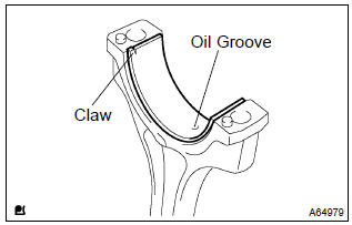
- Align the connecting rod bearing claw with the oil groove of the connecting rod.
- install the connecting rod bearing in the connecting rod.
Notice
: do not apply engine oil to the bearing and its contact surface.
34. Install connecting rod sub–assy
- Position the piston rings so that the ring ends are as shown.
- apply engine oil to the cylinder walls, pistons, and surfaces of the connecting rod bearings.
- check the position of the piston ring ends.
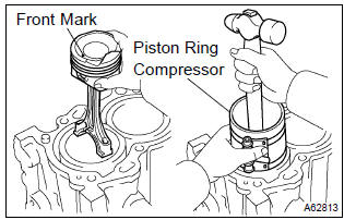
- Using a piston ring compressor, push the correctly numbered piston and connecting rod assemblies into each cylinder with the front mark of the piston facing forward.
- Align the pin dowels of the connecting rod cap with the pins of the connecting rod, then install the connecting rod.
Notice
:
- clean the backside and surface of the connecting rod cap bearing and let not stick the oils and fats.
- Match the numbered connecting rod cap with the same numbered connecting rod.
- check that the protrusion of the connecting rod cap is facing the correct direction.
- apply a light coat of engine oil on the threads and under the heads of the connecting rod cap bolts.
- Using sst, tighten the bolts in several passes by the specified
torque.
Sst 09205–16010 torque: 20 nvm (204 Kgf·cm, 15 ft·lbf)
- Mark the front of the connecting cap bolts with paint.
- retighten the cap bolts by 90 as shown in the illustration.
- check that the crankshaft turns smoothly.
35. Install cylinder block water drain cock sub–assy
- Apply 2 or 3 threads of adhesive to the cylinder block water
drain cock, then install it within 3 minutes.
Torque: 25 nvm (255 Kgf·cm, 18 ft·lbf) adhesive:
part no. 08833–00080, Three bond 1344, loctite 242 or equivalent - after applying the specified torque, rotate the cylinder block water drain cock clockwise until its drain port faces downward.
Notice
:
- do not put into coolant in an hour of installation.
- Do not rotate the drain union more than 360 in (b), and never loosen it after setting the union correctly.


Other materials:
Manual transaxle oil
On–vehicle inspection
1. Inspect transaxle oil
Stop the vehicle on the level place.
remove the transmission filler plug and gasket.
check that the oil surface is within 5 mm (0.20 In.) From the
lowest position of the inner surface of the transmission filler
plug openin ...
Adjustment
1. Headlight aim only
place the vehicle in the following conditions.
The area around the headlight is not deformed.
The vehicle is parked on a level surface.
Tire inflation pressure is in the specified value .
A driver is in the driver’s seat and the vehicle is in a state rea ...
Folding the mirrors
Push the mirror back in the direction of the vehicle’s rear.
■Mirror angle can be adjusted when
► Vehicles without a smart key system
The engine switch is in the “ACC” or “ON” position.
►Vehicles with a smart key system
The engine switch is in ACCESSORY or IGNITION ...