
Toyota Corolla (E120) 2002–2008 Repair Manual / Diagnostics / ABS with EBD system / Open/B+ short circuit in abs motor relay
circuit / Inspection procedure
Toyota Corolla (E120): Inspection procedure
Hint
: start the inspection from step 1 in case of using the hand–held tester and start from step 2 in case of not using the hand–held tester.
1 Perform active test by hand–held tester(abs motor relay)
- Check the operation sound of the abs motor individually when operaing it
with the hand–held tester.
Ok: the operation sound of the abs motor should be heard.


2 Inspect skid control ecu connector(+bm terminal voltage)
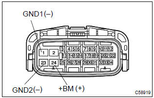
- Disconnect the skid control ecu connector.
- measure the voltage between terminals +bm (24) and
gnd (1, 23) of skid control ecu harness side connector.
Voltage: 10 – 14 v


3 Inspect fuse(abs no.2 Fuse)
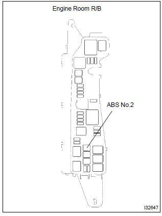
- Remove abs no.2 Fuse from the engine room r/b.
- check continuity of abs no.2 Fuse.
Ok: continuity


4 Inspect skid control ecu connector(gnd terminal continuity)
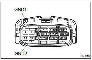
- Measure resistance between terminal gnd (1,23) of skid
control ecu harness side connector and body ground.
Resistance: 1 Ω or less


Check and replace brake actuator assy


Other materials:
Rear seats
► Type A
1 Up
Pull the head restraints up.
2 Down
Push the head restraint down while pressing the lock release button.
► Type B
1 Up
Pull the head restraints up.
2 Down
Push the head restraint down while pressing the lock release button.
■Removing the head restraints ...
Automatic door locking and unlocking systems
The following functions can be set or cancelled:
*1: Vehicles with an automatic transmission or continuously variable transmission
*2: Vehicles with a smart key system
■ Setting and canceling the functions
To switch between set and canceled, follow the procedure below:
1 Vehicles withou ...
Deleting a registered phone number
1 Select “Delete contacts” using .
2 Select the desired phone number using
and press
(YES).
To delete all of the registered phone numbers, select “All delete” using
and press
(YES). ...