Toyota Corolla (E120) 2002–2008 Repair Manual / Introduction / How to troubleshoot ecu controlled
systems / Diagnostic trouble code chart
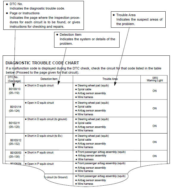
Toyota Corolla (E120): Diagnostic trouble code chart
The inspection procedures are shown in the table below. This table allows efficient and accurate troubleshooting using the diagnostic trouble codes displayed in the diagnostic trouble code chart. Proceed with troubleshooting in accordance with the inspection procedures listed in the diagnostic chart corresponding to the diagnostic trouble codes displayed. The diagnostic trouble code chart for the supplemental restraint system is shown below as an example.


Other materials:
Engine rear oil seal
Replacement
1. Remove manual transaxle assy (m/t transaxle)
2. Remove automatic transaxle assy (a/t transaxle)
3. Remove clutch cover assy (m/t transaxle)
remove the 6 bolts and clutch cover.
4. Remove clutch disc assy (m/t transaxle)
5. Remove flywheel sub–assy (m/t transaxle ...
Inspection procedure
1 Check wire harness(airbag sensor assy center – front seat inner
belt assy lh)
Disconnect the negative (–) terminal cable from the battery,
and wait at least for 90 seconds.
disconnect the connectors between the airbag sensor
assy center and the front seat inner belt assy ( ...
Cd cannot be taken out
Wiring diagram
Inspection procedure
1 Check if radio auto–search functions properly
Check if the radio auto–search function properly.
Perform the auto–research of the radio and check that the
operation is normal.
Standard: malfunction disappear.
2 Press ”eject†...