Toyota Corolla (E210): Meter display
■ Locations of gauges and meters
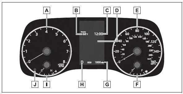
The units of measure may differ depending on the intended destination of the vehicle.
- Tachometer
Displays the engine speed in revolutions per minute - Outside temperature
Displays the outside temperature within the range of -40ºF (-40ºC) to 140ºF (60ºC) - Clock
- Multi-information display Presents the driver with a variety of vehicle data Displays warning messages if a malfunction occurs
- Speedometer
- Fuel gauge
Displays the quantity of fuel remaining in the tank - Odometer and trip meter display
- Shift position indicator
- Engine coolant temperature gauge Displays the engine coolant temperature
- Display change button
■Outside temperature display
- In the following situations, the correct
outside temperature may not
be displayed, or the display may
take longer than normal to
change:
- When stopped, or driving at low speeds (less than 12 mph [20 km/h] )
- When the outside temperature has changed suddenly (at the entrance/exit of a garage, tunnel, etc.)
- When "--" or "E" is displayed, the
system may be malfunctioning.
Take your vehicle to your Toyota dealer.
■Customization
The gauges and meters can be customized
in  of the multi-information
display.
of the multi-information
display.
WARNING
■The information display at low temperatures
Allow the interior of the vehicle to warm up before using the liquid crystal information display. At extremely low temperatures, the information display monitor may respond slowly, and display changes may be delayed.
For example, there is a lag between the driver's shifting and the new gear number appearing on the display. This lag could cause the driver to downshift again, causing rapid and excessive engine braking and possibly an accident resulting in death or injury.
NOTICE
■To prevent damage to the engine and its components
- Do not let the indicator needle of the tachometer enter the red zone, which indicates the maximum engine speed.
- The engine may be overheating if the engine coolant temperature gauge is in the red zone (H). In this case, immediately stop the vehicle in a safe place, and check the engine after it has cooled completely.


Other materials:
Inspection procedure
1 Inspect transmission wire(s1)
Disconnect the transmission wire connector from the
transaxle.
measure the resistance according to the value(s) in the
table below.
Standard:
2 Check harness and connector(transmission wire – ecm)
Connect the transmission connec ...
Temporarily engaged gear steps selection mode in the D position
To drive in temporary gear steps selection mode, operate the “-” and “+” paddle
shift switches. The gear steps can then be selected by operating the “-” and “+”
paddle shift switches. By selecting gear step using paddle shift switches, you can
control engine braking forces.
1 ...
How to proceed with troubleshooting
Hint:
troubleshooting of the wireless door lock control system is based on
the premise that the power door
lock system is operating normally. Therefore, before troubleshooting the
wireless door lock control system,
first make certain that the the power door lock system is operating
...