Toyota Corolla (E120) 2002–2008 Repair Manual / Diagnostics / Sfi system / Readiness monitor drive pattern / Catalyst monitor (o2s type)
Toyota Corolla (E120): Catalyst monitor (o2s type)
- Preconditions
The monitor will not run unless:
- mil is off.
- Engine coolant temperature (ect) is 176°f (80 °C) or greater.
- Intake air temperature (iat) is 14°f (–10 °C) or greater.*
Notice
: * 2002 and later my vehicles: the readiness test can be completed in cold ambient conditions (less than 14°f / –10 °C), if the drive pattern is repeated a second time after cycling the ignition off.
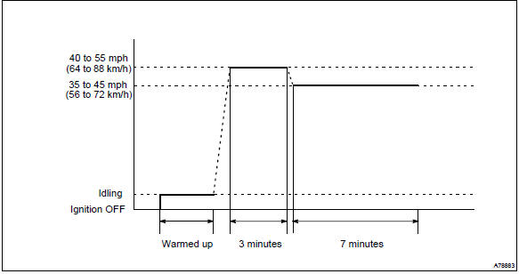
- Drive pattern
- connect the obd ii scan tool to the dlc3 to check monitor status and preconditions.
- Drive the vehicle at 40 to 55 mph (64 to 88 km/h) for approximately 3 minutes.
Notice
: drive with smooth throttle operation and avoid sudden acceleration.
If iat is less than 50°f (10 °C) when starting engine, continue to drive vehicle at 40 to 55 mph (64 to 88km/h) for approximately 4 minutes.
- Drive the vehicle at 35 to 45 mph (56 to 72 km/h) for approximately 7 minutes.
Notice
: drive with smooth throttle operation and avoid sudden deceleration as much as possible with the throttle fully closed.
- If readiness status dose not switch to complete, make sure that the preconditions are met and the ignition switch is turned off and then repeat steps (2) and (3).
- Release pressure in the fuel tank by removing and then reinstalling the fuel tank cap.
- Start the engine and immediately begin driving as directed.


Other materials:
Replacement
Hint: components:
1. Precaution
2. Disconnect battery negative terminal
3. Remove front door scuff plate rh
4. Remove rear door scuff plate rh
5. Remove front door opening trim rh
6. Remove rear door opening trim rh
7. Remove lap belt outer anchor cover
8. Remove center pillar garnis ...
Switching the display
Press to display or hide the album
title.
If there is additional text, is
displayed.
Press and hold to display the remaining
text.
■USB memory functions
●Depending on the USB memory that is connected to the system, the device itself
may not be operable and certain function ...
Problem symptoms table
Hint:
proceed with troubleshooting of each circuit in the table below.
Symptom
Suspect area
When the ignition switch is in the on position, the srs warning
light sometimes comes on after approximately 6 seconds.
Srs warning light ci ...