Toyota Corolla (E170) 2014–2019 Owners Manual / For safety and security / For safe use / Before driving
Toyota Corolla (E170): Before driving
Floor mat
Use only floor mats designed specifically for vehicles of the same model and model year as your vehicle. Fix them securely in place onto the carpet.
1 Insert the retaining hooks (clips) into the floor mat eyelets.
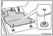
2 Turn the upper knob of each retaining hook (clip) to secure the floor mats in place.
*: Always align the  marks.
The shape of the retaining hooks (clips) may differ from that shown in the illustration.
CAUTION
Observe the following precautions.
Failure to do so may cause the driver’s floor mat to slip, possibly interfering with the pedals while driving. An unexpectedly high speed may result or it may become difficult to stop the vehicle, leading to an accident, or leading to death or a serious injury.
■When installing the driver’s floor mat
●Do not use floor mats designed for other models or different model year vehicles, even if they are Toyota Genuine floor mats.
●Only use floor mats designed for the driver’s seat.
●Always install the floor mat securely using the retaining hooks (clips) provided.
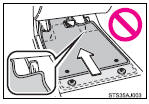
●Do not use two or more floor mats on top of each other.
●Do not place the floor mat bottom-side up or upside-down.
■Before driving
●Check that the floor mat is securely fixed in the correct place with all the provided retaining hooks (clips). Be especially careful to perform this check after cleaning the floor.
●With the engine stopped and the shift lever in P (automatic transmission or continuously variable transmission) or N (manual transmission), fully depress each pedal to the floor to make sure it does not interfere with the floor mat.


Other materials:
Cleaning and protecting the vehicle interior
The following procedures will help protect your vehicle’s interior and keep
it in top condition:
Protecting the vehicle interior
Remove dirt and dust using a vacuum cleaner. Wipe dirty surfaces with a cloth
dampened with lukewarm water.
Cleaning the synthetic leather areas
● Remove l ...
Circuit description
Refer to dtc c0200/31, c0205/32, c1235/35, c1236/36
Hint:
Dtc no. C0210/33, c1238/38 is for the right rear speed sensor.
Dtc no. C0215/34, c1239/39 is for the left rear speed sensor.
Wiring diagram
...
For safe driving
For safe driving, adjust the
seat and mirror to an appropriate
position before driving.
Correct driving posture
Adjust the angle of the seatback
so that you are sitting
straight up and so that you do
not have to lean forward to
steer.
Adjust the seat so that you
can depress the pedals fully ...