Toyota Corolla (E120): Adjustment
1. Check and adjust brake pedal height
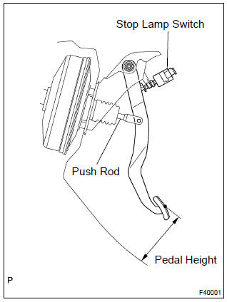
- Inspect brake pedal height.
Pedal height from asphalt sheet: m/t: 134.9 – 144.9 Mm (5.311 – 5.703 In.) A/t: 136.0 – 146.0 Mm (5.353 – 5.747 In.)
- Disconnect the connector from the stop lamp switch.
- Remove the stop lamp switch.
- Loosen the clevis lock nut.
- Adjust the pedal height by turning the pedal push rod.
- Tighten the push rod lock nut.
Torque: 26 nvm (265 Kgf·cm, 19 ft·lbf)
- install the stop lamp switch.
- Connect the connector to the stop lamp switch.
- Push the brake pedal in 5 – 15 mm (0.20 – 0.59 In.), And turn the stop lamp switch to lock the nut in the position where the stop lamp goes off.
- After installation, push the brake pedal in 5 – 15 mm (0.20 – 0.59 In.), Check that stop lamp comes on.
2. Check pedal free play
- Stop the engine and depress the brake pedal several times until there is no more vacuum left in the booster.
- push in the pedal until the beginning of the resistance is
felt. Measure the distance, as shown in the installation.
Pedal free play: 1 – 6 mm (0.04 – 0.24 In.)
If incorrect, check the stop lamp switch clearance.
If the clearance is ok, then troubleshoot the brake system.
Stop lamp switch clearance: 0.5 – 2.4 Mm (0.020 – 0.094 In.)
3. Check pedal reserve distance
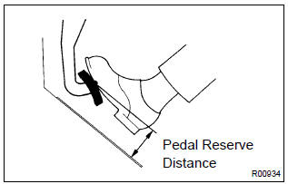
- Release the parking brake lever.
With engine running, depress the pedal and measure the pedal reserve distance, as shown in the installation.
Pedal reserve distance from asphalt sheet at 490 n (50 kgf, 110.2 Lbf): more than 70 mm (2.76 In.)
If incorrect, troubleshoot the brake system.


Other materials:
Automatic transmission / trans
Preparation
Sst
Recomended tools
Equipment
Lubricant
Ssm (special service materials)
...
Wireless remote control/electronic key battery
Replace the battery with a new one if it is depleted.
You will need the following items:
● Flathead screwdriver
● Small flathead screwdriver
● Lithium battery CR2016 (vehicles without a smart key system), or CR2032 (vehicles
with a smart key system)
Replacing the battery
&# ...
Inspection procedure
1 Check seat position air bag sensor
Sst 09843–18040
Turn the ignition switch to on, and wait at least for 20 seconds.
clear the dtc stored in memory .
turn the ignition switch to lock, and wait at least for 20
seconds.
turn the ignition switch to on, and wait at ...